EasyManua.ls Logo

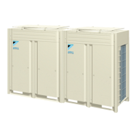
Daikin REMQ14P8Y1B User Manual

Daikin REMQ14P8Y1B
36 pages
To Next Page IconTo Next Page
Page #1 background imageLoading...
Page #1 background image
INSTALLATION MANUAL
REMQ8P9Y1B
REMQ10P8Y1B
REM(H)Q12P8Y1B
REMQ14P8Y1B
REMQ16P8Y1B
System air conditioner

Table of Contents

Question and Answer IconNeed help?

Do you have a question about the Daikin REMQ14P8Y1B and is the answer not in the manual?

Daikin REMQ14P8Y1B Specifications

General IconGeneral
BrandDaikin
ModelREMQ14P8Y1B
CategoryAir Conditioner
LanguageEnglish

Summary

VRV System Installation Overview

VRV Unit Combinations and Accessories

Details possible combinations of outdoor/indoor units and standard/optional accessories.

Technical Specifications Reference

Refers to the Engineering Data Book for detailed technical and electrical specifications.

Main Components of VRV Systems

VRV Installation Location Selection

General VRV Location Requirements

Covers foundation, space, fire danger, noise, wind, salt, and access considerations for unit placement.

Prohibited VRV Installation Locations

Lists locations to avoid for installation, such as corrosive atmospheres or high electromagnetic fields.

VRV Unit Inspection and Handling

VRV Unit Unpacking and Placement

VRV Refrigerant Piping Installation

Installation Tools for R410A Systems

Lists specialized tools required for R410A refrigerant piping installations.

Selecting Refrigerant Piping Materials

Specifies requirements for piping material, temper grade, and thickness for R410A systems.

Refrigerant Pipe Connection Procedures

Details the correct methods for connecting refrigerant pipes, emphasizing nitrogen blow and flux usage.

Connecting Refrigerant Piping to Outdoor Units

Removing Pinched Refrigerant Piping

Provides a step-by-step guide on how to safely remove pinched refrigerant piping.

VRV Outdoor Unit Piping Connections

Precautions for Multi-Unit Outdoor Piping

Covers precautions and requirements for connecting piping between multiple outdoor units.

VRV Multi-Unit Piping Patterns

Illustrates various valid and prohibited piping connection patterns for multi-unit systems.

Branching Refrigerant Piping with Kits

VRV Piping Length Restrictions

Preventing Contamination During Pipe Installation

Example VRV Refrigerant Piping Connections

Selecting Refnet Joints for VRV Systems

Guide on selecting the appropriate refnet joint based on outdoor unit capacity.

Selecting Refnet Headers for VRV Systems

Guide on selecting the appropriate refnet header based on total indoor unit capacity.

Choosing VRV Multi-Connection Piping Kits

Guide on selecting multi connection piping kits based on the number of outdoor units.

VRV Refrigerant Pipe Size Selection

Calculating Additional VRV Refrigerant Charge

VRV Leak Test and Vacuum Drying

Performing VRV System Airtightness Test

Instructions on how to conduct an airtightness test using nitrogen gas.

VRV Field Wiring Installation

Internal Wiring Component Table

Lists and explains abbreviations for internal wiring components used in VRV units.

VRV Optional Parts Connectors

VRV Power Circuit and Cable Requirements

General VRV Installation Cautions

VRV System Wiring Examples

Routing VRV Power and Transmission Lines

Field Connecting VRV Transmission Wiring

Field Connecting VRV Power Wiring

Precautions for Laying VRV Power Wiring

Wiring Examples Inside VRV Units

VRV Unit and Installation Condition Checks

VRV Piping Work Checks

Verifies correct piping size and insulation work before system operation.

VRV Electrical Work Checks

Confirms proper power, transmission wiring, and insulation resistance.

VRV Refrigerant Charging

Important Information on R410A Refrigerant

Provides key details about R410A refrigerant, including its type and GWP.

Precautions for Adding R410A Refrigerant

VRV Stop Valve Operation Procedure

Checking Connected VRV Units

VRV Additional Refrigerant Charge Procedure

VRV Refrigerant Charging in Cooling Mode

VRV Refrigerant Charging in Heating Mode

Inputting Additional Refrigerant Charge Weight

Post-Refrigerant Charge Checks

VRV System Pre-Operation Checks

Service Precautions for Inverter Equipment

Important safety precautions when performing service on VRV inverter units.

VRV Fan Safety Precautions

VRV Initial Start-up Checks

VRV PCB Dip Switches, LEDs, and Buttons

VRV Mode Setting Procedures

Setting Mode 1 Configuration

Describes the default setting mode and its conditions for VRV units.

Setting Mode 2 Configuration

Explains how to enter and use setting mode 2 for advanced configuration.

Confirming VRV System Set Modes

VRV System Test Operation Guide

Step-by-Step Test Operation Procedure

A detailed procedure for executing the VRV system test operation.

Correcting Abnormal Test Operation Results

Actions to take if the test operation results in an error code or abnormality.

Final Checks After VRV Installation

VRV Service Mode Operations

VRV Vacuuming Procedure for Service

Details the process of vacuuming the VRV system for repair purposes.

VRV Refrigerant Recovery Operation

Outlines the method for recovering refrigerant using specialized equipment.

Additional VRV Refrigerant Charging Methods

Caution for Refrigerant Leaks in VRV Systems

VRV Refrigerant Maximum Concentration Levels

Explains how to calculate and manage maximum allowable refrigerant concentration.

Checking Maximum Refrigerant Concentration

VRV Unit Disposal Requirements

Related product manuals