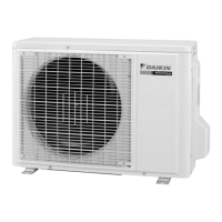
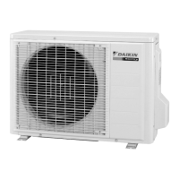
Do you have a question about the Daikin RKS25G2V1B9 and is the answer not in the manual?
Lists all functions for cooling-only and heat pump models.
Details the functions available for cooling-only air conditioner models.
Details the functions available for heat pump air conditioner models.
Provides detailed technical specifications for the air conditioning units.
Detailed technical specifications specifically for cooling-only units.
Detailed technical specifications specifically for heat pump units.
Illustrates the wiring diagrams for PCBs and connectors in the system.
Wiring details for indoor unit printed circuit boards and their connectors.
Wiring details for outdoor unit printed circuit boards and their connectors.
Explains core operational functions like Frequency Principle and Airflow Control.
Explains the inverter principle and frequency control of the compressor.
Details how to adjust airflow direction using flaps and louvers.
Describes how the unit automatically selects cooling or heating mode.
Explains the energy-saving operation to reduce power consumption.
Describes the sensor-based airflow control for human presence.
Details system control specifications like Mode Hierarchy and Frequency Control.
Details how frequency is determined based on temperature differences.
Explains how input current limits compressor frequency.
Lists and describes common malfunctions and their detection methods.
Explains the forced cooling operation mode.
Provides guidance on system setup and user handling post-installation.
Operation details for FTXS series models, including remote control and modes.
Identifies and describes the buttons and functions of the remote control.
Explains how to start, stop, and change operation modes.
Explains sensor-based airflow control for comfort and energy saving.
Describes how to maximize cooling/heating effect for maximum capacity.
Details the energy-saving operation by limiting power consumption.
Describes how to set up to 4 timer settings per day for weekly scheduling.
Operation details for ATXS series models, including remote control and modes.
Identifies and describes the buttons and functions of the remote control.
Explains how to start, stop, and change operation modes.
Explains airflow direction adjustments for comfortable airflow.
Describes the motion sensor function for energy saving.
Explains how to use OFF TIMER and ON TIMER functions.
Important warnings and procedures before starting diagnostic checks.
Guides on troubleshooting using indoor and outdoor unit LED indicators.
Common operational issues and recommended troubleshooting steps.
Provides detailed troubleshooting steps for various system errors.
Comprehensive list and explanation of all error codes displayed on the remote.
Troubleshooting steps for abnormal indoor unit PCB function.
Diagnostic procedures for protection control errors like freeze-up.
Outlines troubleshooting steps for fan motor issues.
Guides on troubleshooting thermistor issues in the indoor unit.
Troubleshooting for communication errors between indoor and outdoor units.
Troubleshooting steps for abnormal outdoor unit PCB function.
Diagnostic procedures for compressor overload conditions.
Troubleshooting steps for compressor lock errors.
Methods and procedures for detecting and addressing refrigerant shortage.
Step-by-step instructions for disassembling the indoor air conditioning unit.
Step-by-step guide to remove the air filter from the indoor unit.
Instructions for safely removing the front panel of the indoor unit.
Guide for removing the electrical box from the indoor unit.
Instructions for removing printed circuit boards from the indoor unit.
Procedures for removing components from specific outdoor unit models.
Instructions for removing outer panels and the fan motor.
Guide for removing the electrical box from the outdoor unit.
Instructions for removing printed circuit boards from the outdoor unit.
Procedure for safely removing the compressor.
Component removal steps for specific outdoor unit models.
Instructions for removing outer panels.
Steps to remove the outdoor fan and fan motor.
Procedure for safely removing the compressor.
Component removal steps for specific outdoor unit models.
Steps to remove the outdoor fan and fan motor.
Procedure for safely removing the compressor.
Procedures for conducting trial operation to verify system functionality and user satisfaction.
Details on configuring unit settings like model type and standby power saving.
Instructions for setting the unit's model type using DIP switches.
Procedure to enable the standby electricity saving function for energy conservation.
Explains jumper/switch settings to expand operation range at low outdoor temperatures.
Schematic diagrams illustrating refrigerant piping configurations for indoor and outdoor units.
Refrigerant piping diagrams for indoor units.
Refrigerant piping diagrams for outdoor units.
Electrical wiring diagrams for indoor and outdoor unit components and PCBs.
Electrical wiring diagram for the indoor unit.
Electrical wiring diagram for the outdoor unit.
| Cooling Capacity | 2.5 kW |
|---|---|
| Heating Capacity | 3.2 kW |
| Power Supply | 220-240V, 50Hz |
| Refrigerant | R32 |
| Type | Split AC |
| Noise Level (Indoor Unit) | 19 dB(A) |

