Do you have a question about the Daikin RX36NMVJU and is the answer not in the manual?
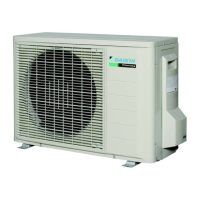
Details the technical specifications for cooling-only models, including capacity, power, and dimensions.
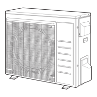
Details the technical specifications for heat pump models, including capacity, power, and dimensions.
Explains how compressor frequency is determined based on temperature and other controls.
Explains controls to prevent freezing and manage heating peak loads.
Outlines conditions and timing for starting and canceling defrost cycles.
Lists control items for the electronic expansion valve including open and feedback controls.
Identifies sensors prone to malfunction and detection of overcurrent/overload.
Lists common symptoms and initial checks for troubleshooting unit operation issues.
Guides on troubleshooting using indoor and outdoor unit LED indicators.
Details the meaning of the operation lamp blinking on the indoor unit.
Provides two methods for diagnosing errors using the remote controller.
Details initial steps for diagnosing errors using Method 2, including button presses.
Continues diagnostic steps for Method 2, including sound diagnosis and error code determination.
Introduces the section detailing troubleshooting for various error codes.
Explains error A1, its causes, and troubleshooting steps for indoor unit PCB issues.
Provides a visual guide for diagnosing indoor unit PCB problems step-by-step.
Details error A5 related to freeze-up protection and heating peak-cut control.
Explains error A6 concerning indoor fan motor issues and their potential causes.
Provides a visual guide for diagnosing indoor fan motor problems step-by-step.
Covers errors C4 and C9 related to indoor unit thermistors and their troubleshooting.
Explains error U2 related to power supply voltage abnormalities and their causes.
Provides a visual guide for diagnosing power supply voltage issues step-by-step.
Details error U4 concerning communication issues between indoor and outdoor units.
Provides a visual guide for diagnosing indoor/outdoor unit communication errors.
Explains error U7 related to communication on the outdoor unit PCB and its causes.
Covers error UA for incompatible unit combinations or wiring issues.
Explains error E1 related to outdoor unit PCB malfunctions and troubleshooting.
Details error E5 indicating compressor overload or OL activation and its causes.
Provides a visual guide for diagnosing compressor overload issues step-by-step.
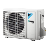
| Cooling Capacity | 3.6 kW |
|---|---|
| Refrigerant | R32 |
| Heating Capacity | 4.0 kW |
| Outdoor Unit Weight | 32 kg |
| Type | Split System |
| Power Supply | 220-240 V, 50 Hz |