Do you have a question about the Daikin RXMQ4·5·6PVE and is the answer not in the manual?
Lists model names for indoor and outdoor units.
Provides visual representations of indoor unit appearances.
Details the capacity ranges for outdoor and indoor units.
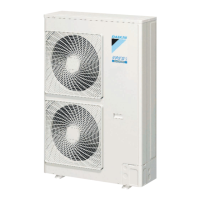
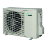
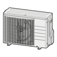
Presents technical specifications for outdoor units like cooling/heating capacity, dimensions, and components.
Provides technical specifications for various indoor unit types, including capacity and sound level.
Lists electrical and functional parts for the outdoor unit, including compressor, fan motor, and sensors.
Lists electrical and functional parts for various indoor units, including remote controllers, motors, and thermistors.
Details the refrigerant circuit diagram and major components for outdoor units.
Shows the functional parts layout for the outdoor unit with component identification.
Explains the different operational modes and their flowcharts.
Describes basic control operations for cooling and heating modes.
Details special control functions like startup, oil return, and defrosting operations.
Outlines various protection controls such as high pressure, low pressure, and inverter protection.
Provides critical safety cautions and warnings for repair work, including pictograms.
Lists specific warnings and safety measures to observe during repair procedures.
Safety advice related to post-repair installation and handling of the equipment.
Procedures and checks to perform after completing repair work for safety and functionality.
Explains the purpose of icons used in the manual for drawing attention to specific information.
Provides a list and explanation of the icons used in the manual.
Outlines the procedure and overview for conducting initial test operations after installation.
Explains how to configure system settings using remote controllers or outdoor unit dip switches.
Details how to perform field settings using wired and wireless remote controllers.
Step-by-step guide for setting up functions using the wired remote controller.
Explains setting contents and corresponding code numbers for VRV indoor units.
Table indicating the applicable range of field settings for different indoor unit types.
Detailed explanation of various setting modes, including filter sign and fan speed settings.
Procedures for setting group numbers for centralized control using remote controllers.
Details the specific settings made via dip switches on the outdoor unit PC board.
Describes the four modes for switching between cooling and heating operations.
Instructions for setting cool/heat modes using a cool/heat switching remote controller.
Details how to set low noise operation using external contact inputs and remote controller settings.
Explains how to set demand operation to save power consumption by limiting compressor output.
Lists and explains the different contents of control modes available for setting.
Provides troubleshooting steps based on observed system symptoms and their supposed causes.
Explains troubleshooting methods using remote controller functions like inspection and self-diagnosis.
Lists and explains troubleshooting steps for various malfunction codes displayed on the remote controller.
Details how to use the INSPECTION/TEST button to access various modes for troubleshooting.
Explains the self-diagnosis procedure for wired remote controllers to identify malfunctions.
Describes the self-diagnosis process for wireless remote controllers to identify malfunctions.
Outlines the sequence of operations when using the remote controller's inspection/test functions.
Explains how to enter and utilize the remote controller's service mode for advanced settings.
Details the self-diagnosis function of the remote controller for maintenance and troubleshooting.
Troubleshooting steps for "A0" error, indicating an external protection device issue.
Troubleshooting steps for "A1" error, indicating a defect in the indoor unit's PC board.
Troubleshooting for "A3" error related to drain level control system malfunction.
Troubleshooting steps for "A6" error indicating fan motor lock or overload.
Troubleshooting for "A7" error related to swing flap motor malfunction.
Troubleshooting for "A9" error, indicating a moving part malfunction in the electronic expansion valve.
Troubleshooting for "AJ" error related to a malfunction in the capacity determination device.
Troubleshooting for "C4" error, indicating a malfunction of the heat exchanger thermistor.
Troubleshooting for "C5" error, indicating a malfunction of the gas pipe thermistor.
Troubleshooting for "C9" error, indicating a malfunction of the suction air thermistor.
Troubleshooting for "CA" error, indicating a malfunction of the discharge air thermistor.
Troubleshooting for "CJ" error, indicating a malfunction of the remote controller's thermostat sensor.
Troubleshooting for "E3" error, indicating actuation of the high pressure switch.
Troubleshooting for "E4" error, indicating actuation of the low pressure sensor.
Troubleshooting for "E5" error, indicating a compressor motor lock condition.
Troubleshooting for "E7" error, indicating a malfunction of the outdoor unit fan motor.
Troubleshooting for "E9" error, indicating a moving part malfunction in the electronic expansion valve.
Troubleshooting for "F3" error, indicating abnormal discharge pipe temperature.
Troubleshooting for "F6" error, indicating refrigerant overcharge.
Troubleshooting for "H9" error, indicating a malfunction of the outdoor air thermistor.
Troubleshooting for "J3" error, indicating a malfunction of the discharge pipe thermistor.
Troubleshooting for "J5" error, indicating a malfunction of the suction pipe thermistors.
Troubleshooting for "J7" error, indicating a malfunction of the outdoor unit liquid pipe thermistor.
Troubleshooting for "J9" error, indicating a malfunction of the subcooling heat exchanger gas pipe thermistor.
Troubleshooting for "JC" error, indicating a malfunction of the low pressure sensor.
Troubleshooting for "L4" error, indicating a malfunction related to inverter radiating fin temperature rise.
Troubleshooting for "L8" error, indicating an abnormal inverter current.
Troubleshooting for "L9" error, indicating an inverter start-up error.
Troubleshooting for "LC" error, indicating a transmission malfunction between inverter and control PC boards.
Troubleshooting for "P4" error, indicating a malfunction of the inverter radiating fin temperature rise sensor.
Troubleshooting for "U2" error, indicating insufficient or instantaneous power supply failure.
Troubleshooting for "U3" error, indicating that check operation was not executed.
Troubleshooting for "U4" error, indicating a transmission malfunction between indoor and outdoor units.
Troubleshooting for "U5" error, indicating a transmission malfunction between remote controller and indoor unit.
Troubleshooting for "U9" error, indicating transmission malfunction within the same system.
Troubleshooting for "UA" error, indicating an excessive number of indoor units connected.
Troubleshooting for "UE" error, indicating transmission malfunction between central remote controller and indoor unit.
Troubleshooting for "UF" error, indicating the system is not yet set.
Troubleshooting for "UH" error, indicating system or refrigerant system address undefined.
Troubleshooting for "UE" error related to transmission between centralized remote controller and indoor unit.
Troubleshooting for "M1" error, indicating a PC board defect in the centralized controller.
Troubleshooting for "M8" error, indicating transmission malfunction between optional controllers.
Troubleshooting for "MA" error, indicating improper combination of optional controllers.
Troubleshooting for "MC" error, indicating address duplication or improper setting.
Troubleshooting steps when the operation lamp blinks on the Unified ON/OFF controller.
Troubleshooting for single blink display of "Under Host Computer Integrate Control".
Troubleshooting for double blink display of "Under Host Computer Integrate Control".
Provides piping diagrams for outdoor and indoor units.
Contains wiring diagrams for outdoor, field, and indoor units.
Lists available optional accessories for controllers and PC boards.
Illustrates examples of system connections for indoor and outdoor units, including refnet joints and headers.
Provides resistance and temperature data for indoor and outdoor unit thermistors.
Explains the characteristics and voltage output of high and low pressure sensors.
Step-by-step guide for replacing inverter power transistor modules on the PC board.
Wiring diagrams for outdoor units.
Illustrates field wiring connections between outdoor and indoor units.
Wiring diagrams for various indoor unit models.
Lists various optional controllers and their compatibility.
Lists optional accessories available for outdoor units.
Provides essential precautions for handling the new R-410A refrigerant.
Gives an overview of R-410A refrigerant characteristics, pressure, and composition.
Details specifications and handling procedures for R-410A refrigerant cylinders.
Lists and describes the specific tools required for servicing R-410A systems.
| Brand | Daikin |
|---|---|
| Model | RXMQ4·5·6PVE |
| Category | Air Conditioner |
| Language | English |