17 | Technical data
Installer reference guide
67
RXTM30+40N2V1B + RXTP25+35N2V1B9 + RXTP25+35N2V1B8 +
ARXTP25+35N2V1B + RXTA30N2V1B
R32 split series
4P518023-7H – 2020.08
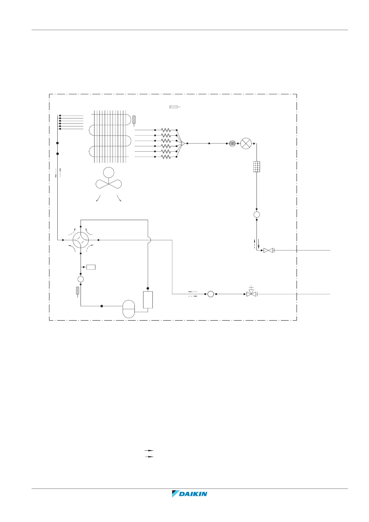
17.2 Piping diagram
17.2.1 Piping diagram: Outdoor unit
PED categories of equipment – High pressure switch: category IV; Compressor: category II; Other equipment:
art. 4§3.
M
p
l
q
c
d
a
b
o
n
g
m
m
m
r
·6x7.0· CuT
·7.9· CuT
·6.4· CuT
·6.4· CuT
·9.5· CuT
·7.9· CuT
·9.5· CuT
·9.5· CuT
·12.7· CuT
·9.5· CuT
·9.5· CuT
·9.5· CuT
·6x7.0· CuT
HPS
·6.4· CuT
k
·12.7· CuT
·6x3.2· CuT
·6.4· CuT
f
h
i
j
e
a Field piping (liquid)
b Field piping (gas)
c Liquid stop valve
d Gas stop valve
e Filter
f Electronic expansion valve
g Muffler with filter
h Distributor
i Capillary tube
j Heat exchanger
k Heat exchanger thermistor
l Accumulator
m Muffler
n ON: heating 4-way valve
o Discharge pipe thermistor
p Outdoor air temperature thermistor
q Compressor
r Propeller fan
M Fan motor
HPS High pressure switch (Automatic reset)
Cooling
Heating