Do you have a question about the Daikin RXYQ96 and is the answer not in the manual?
Essential safety guidelines for repair work to prevent injury.
Essential safety guidelines for repair work to prevent injury.
Crucial safety advice for handling and installing equipment after repair.
Procedures to verify correct operation and safety after repair completion.
Explanation of symbols used throughout the manual for clarity.
Introductory remarks and overview of the manual's content.
Lists and identifies various indoor and outdoor unit models.
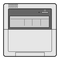
Visual overview of the physical design of indoor and outdoor units.
Displays external views of different indoor unit types.
Shows the physical appearance of various outdoor unit models.
Guidelines and tables for selecting appropriate indoor units for outdoor units.
Detailed technical specifications for system components.
Comprehensive technical data for all outdoor unit models.
Technical specifications for various indoor unit models.
Diagram and explanation of the refrigerant system flow.
Specific refrigerant circuit details for RXYQ72M and 96M models.
Identification and location of key components within the system.
Layout of functional parts for RXYQ72M and 96M models.
Illustrates refrigerant flow paths during different operating conditions.
Overview of the system's different operating modes.
Fundamental control logic for system operation.
Detailed explanation of standard cooling and heating operations.
How PI control maintains stable performance via compressor adjustment.
PI control for electronic expansion valves to optimize evaporator performance.
Fan speed regulation during cooling operation based on conditions.
Specific operational controls for various scenarios.
Procedures for safe and proper system startup.
Methods for ensuring proper oil circulation within the system.
How the system manages defrost cycles to prevent ice buildup.
Process for managing refrigerant during shutdown or specific operations.
System behavior when restarting after a temporary stop.
Procedures for safely stopping system operation.
Steps to equalize pressure before initiating startup.
System safeguards against abnormal operating conditions.
Mechanism to prevent damage from excessive system pressure.
Safeguards to protect compressors from low pressure issues.
Protection against high discharge pipe temperatures to prevent compressor damage.
Safeguards for the inverter against overcurrent and overheating.
Protection against overcurrent to prevent STD compressor damage.
Additional operational control features.
Managing the operating sequence of multiple outdoor units.
Procedures for operating the system in emergency situations.
Controls to manage power consumption based on demand.
Conditions under which heating operation is restricted.
Overview of indoor unit control logic.
Operation logic for the indoor unit drain pump.
How remote controller sensors influence temperature control.
System logic to prevent freezing of indoor unit components.
Procedures for initial system testing after installation.
Step-by-step guide for conducting the initial test operation.
Behavior of the system upon initial power application.
Diagram showing the layout of the outdoor unit's main circuit board.
Configuration settings performed on-site for system optimization.
How to adjust settings using the wired or wireless remote controller.
Procedures for configuring settings directly on the outdoor unit.
Methods for diagnosing issues using the remote controller.
Using the inspection/test button to access diagnostic modes.
Steps for wired remote controller self-diagnosis.
Steps for wireless remote controller self-diagnosis.
Guide to using the inspection/test button functions.
Accessing and using the remote controller's service functions.
How the remote controller diagnoses system faults.
Diagnosing issues based on error codes displayed on the remote controller.
Troubleshooting steps for "A0" error code related to external protection.
Diagnosing and resolving "A1" error for indoor unit PC board issues.
Troubleshooting "A3" error related to the drain level control system.
Diagnosing and fixing "A6" error for fan motor lock or overload.
Troubleshooting "A7" error related to the swing flap motor.
Steps to resolve "A9" error concerning the electronic expansion valve.
Troubleshooting "AF" error indicating a high drain water level.
Diagnosing "AJ" error related to capacity determination faults.
Troubleshooting "C4" error for heat exchanger thermistor failure.
Diagnosing and fixing "C5" error for gas pipe thermistor issues.
Troubleshooting "C9" error for suction air thermistor failure.
Diagnosing and resolving "CJ" error for remote thermostat sensor faults.
Troubleshooting "E1" error indicating an outdoor unit PC board defect.
Steps to address "E3" error related to high pressure switch activation.
Troubleshooting "E4" error caused by low pressure sensor actuation.
Diagnosing and resolving "E5" error for compressor motor lock.
Troubleshooting "E6" error for compressor motor overcurrent or lock.
Steps to fix "E7" error related to outdoor unit fan motor malfunction.
Diagnosing and resolving "E9" error for electronic expansion valve part malfunction.
Troubleshooting "F3" error for abnormal discharge pipe temperature.
Steps to address "F6" error indicating refrigerant overcharge.
Diagnosing "H7" error for abnormal outdoor fan motor signal.
Troubleshooting "H9" error for outdoor air thermistor malfunction.
Diagnosing and resolving "J2" error for current sensor malfunction.
Troubleshooting "J3" error for discharge pipe thermistor malfunction.
Diagnosing and fixing "J5" error for suction pipe thermistor malfunction.
Troubleshooting "J6" error for heat exchanger deicer thermistor malfunction.
Diagnosing and resolving "J7" error for receiver outlet liquid pipe thermistor.
Troubleshooting "J8" error for oil equalizing pipe thermistor malfunction.
Diagnosing and fixing "J9" error for sub-cooling gas pipe thermistor.
Troubleshooting "JA" error for discharge pipe pressure sensor malfunction.
Diagnosing and resolving "JC" error for suction pipe pressure sensor.
Troubleshooting "L4" error for inverter radiating fin temperature rise.
Diagnosing and resolving "L5" error for inverter compressor abnormality.
Troubleshooting "L8" error for inverter current abnormality.
Diagnosing and fixing "L9" error for inverter startup issues.
Troubleshooting "LC" error for communication issues between inverter and control boards.
Diagnosing and resolving "P1" error for inverter over-ripple protection.
Troubleshooting "P4" error for inverter radiating fin temperature sensor.
Diagnosing "PJ" error due to incorrect field settings or PC board combinations.
Troubleshooting "UO" error for low pressure drop issues.
Diagnosing and resolving "U1" error for reverse or open phase power supply.
Troubleshooting "U2" error for insufficient or failed power supply.
Diagnosing and fixing "U3" error when check operation is not performed.
Troubleshooting "U4" error for transmission issues between indoor and outdoor units.
Diagnosing and resolving "U5" error for remote controller to indoor unit communication.
Troubleshooting "U7" error for transmission issues between outdoor units.
Diagnosing and fixing "U8" error for main/sub remote controller communication.
Troubleshooting "U9" error for transmission issues within the same system.
Diagnosing "UA" error for incorrect unit or controller combinations.
Troubleshooting "UC" error for duplicate central remote controller addresses.
Diagnosing and resolving "UE" error for centralized controller to indoor unit communication.
Troubleshooting "UF" error when the system configuration is not set.
Diagnosing and fixing "UH" error for undefined system or refrigerant addresses.
Troubleshooting issues related to central remote controller operation.
Diagnosing and resolving "M1" error for central remote controller PC board defects.
Troubleshooting "M8" error for communication issues between optional controllers.
Diagnosing "MA" error for incorrect optional controller combinations.
Troubleshooting "MC" error for address duplication or improper settings.
Troubleshooting issues related to schedule timer functions.
Diagnosing and resolving "UE" error for transmission issues between central controller and indoor unit.
Troubleshooting "M1" error for schedule timer PC board defects.
Diagnosing "M8" error for communication issues between optional controllers.
Troubleshooting "MA" error for incorrect optional controller combinations.
Diagnosing and resolving "MC" error for address duplication or improper settings.
Troubleshooting issues related to unified ON/OFF controller operation.
Diagnosing issues based on the operation lamp blinking status.
Troubleshooting "Under Centralized Control" blink errors (single repeat).
Diagnosing "Under Centralized Control" blink errors (double repeat).
Step-by-step guide for replacing the inverter compressor.
Detailed instructions for replacing the INV compressor.
Visual diagrams illustrating refrigerant piping configurations.
Piping diagram specific to outdoor units.
Piping diagram specific to indoor units.
Electrical wiring diagrams for system components.
Wiring diagram for outdoor unit electrical connections.
Diagrams showing how field wiring should be connected.
Wiring diagram for indoor unit electrical connections.
Comprehensive list of electrical and functional components.
List of parts for outdoor units.
List of parts for indoor units.
List of available optional accessories for system control.
Options for remote and centralized controllers.
Optional accessories specific to outdoor units.
Illustrations showing typical system connection configurations.
Tables detailing thermistor resistance values at various temperatures.
Information on pressure sensor specifications and characteristics.
Procedures for replacing inverter power transistors and diode modules.
Detailed steps for replacing inverter power components.
Essential safety guidelines and information for using R-410A refrigerant.
General characteristics and properties of R-410A refrigerant.
Recommended tools and compatibility for R-410A refrigerant work.
| Model | RXYQ96 |
|---|---|
| Category | Air Conditioner |
| Refrigerant | R410A |
| Type | VRV |
| Cooling Capacity | 27.0 kW |
| Heating Capacity | 30.0 kW |
| Outdoor Unit Weight | 286 lbs |