EasyManua.ls Logo

Daikin RZQ200MY1 - User Manual

Daikin RZQ200MY1
20 pages
Print Icon
To Next Page IconTo Next Page
Loading...
SPLIT SYSTEM Air Conditioner
OPERATION MANUAL
RZQ180MY1
RZQ200MY1
00_CV_3P529409-2B.indd 1 30/10/2019 16:48:00

Other manuals for Daikin RZQ200MY1

Question and Answer IconNeed help?

Do you have a question about the Daikin RZQ200MY1 and is the answer not in the manual?

Summary

1. Definitions

1.1 Meaning of warnings and symbols

Explains warning symbols and their severity classification in the manual for hazard identification.

1.2 Meaning of used terms

Defines key terms used within the manual, such as 'Installation manual' and 'Operation manual'.

1.3 Safety precautions

Outlines critical safety instructions and warnings to prevent injury and equipment damage.

2. Introduction

2.1 System layout

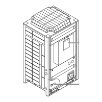
Illustrates the basic components of the air conditioning system, including units and piping.

3. Before operation

4. Remote controller

5. Operation range

6. Operation procedure

6.1 Cooling, heating, fan only, automatic operation and dry operation

Details how to select and use various operating modes like cooling, heating, fan, and dry.

6.1.2 Explanation of heating operation

Explains specific aspects of heating operation, including defrost and hot start functions.

6.2 Program dry operation

Describes the program dry operation for humidity reduction with minimal temperature impact.

7. Energy saving and optimum operation

8. Maintenance

8.1 Maintenance after a long stop period

Provides steps for checking and preparing the unit before seasonal operation after a long stop.

8.2 Maintenance before a long stop period

Outlines procedures for preparing the unit for storage at the end of the operating season.

9. Symptoms that are not air conditioner troubles

9.1 The system does not operate

Explains why the system may not start immediately after power-on or button press.

9.2 Fan operation is possible, but cooling; heating do not work

Addresses situations where the fan runs but cooling/heating is inactive due to initialization.

9.3 White mist comes out of a unit

Explains the cause of white mist, often normal during cooling with high humidity.

9.4 The remote controller display shows “U4” or “U5” and stops, but then restarts after a few minutes

Describes error codes U4/U5, typically caused by electrical noise interfering with communication.

9.5 Noise of air conditioners

Details various normal operational noises and their sources, such as refrigerant flow or expansion.

9.6 Dust comes out of the unit

Explains dust emission, usually occurring when the unit is used after a long period of inactivity.

9.7 The units can give off odours

Discusses how units can absorb and re-emit ambient room odors like smoke or furniture smells.

9.8 The outdoor unit fan does not operate. But compressor still running

Addresses the scenario where the outdoor fan is off but the compressor is active for product optimization.

9.9 The compressor in the outdoor unit does not stop after a short heating operation

Explains the compressor's behavior after short heating cycles to manage oil and refrigerant.

9.10 The inside of an outdoor unit is warm even when the unit has stopped

Explains the function of the crankcase heater warming the compressor for smooth startup.

9.11 Does not cool very well

Provides guidance on diagnosing reduced cooling performance and potential causes.

10. Troubleshooting

11. After-sales service and warranty

11.4 Malfunction codes

Lists various malfunction codes displayed on the remote controller and their corresponding meanings.

11.1 Warranty period

Details the product's warranty coverage and the importance of keeping the warranty card.

11.2 After-sales service

Recommends professional maintenance and inspection contracts for long-term unit performance.

11.3 Shortening of maintenance cycle and replacement cycle

Identifies conditions that may necessitate shorter maintenance and replacement intervals for unit parts.

11.2.2 Recommended inspection and maintenance cycles

Provides recommended intervals for inspection and maintenance of unit components.

Overview

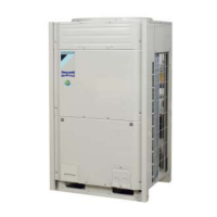
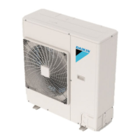
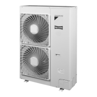
This document is an operation manual for a Daikin SPLIT SYSTEM Air Conditioner, specifically for models RZQ180MY1 and RZQ200MY1. It provides comprehensive instructions for safe and effective operation, maintenance, and troubleshooting.

Function Description

The Daikin Split System Air Conditioner is designed to provide heating, cooling, fan-only operation, automatic operation, and dry operation for indoor environments. It utilizes a refrigerant cycle to transfer heat, ensuring comfortable room temperatures and humidity levels. The system consists of an outdoor unit, refrigerant piping, an indoor unit, and a remote controller for user interaction.

Important Technical Specifications

The system is designed to operate within specific temperature and humidity ranges for optimal performance:

  • Outdoor temperature: -5°C to 43°C DB (Dry Bulb) and -20°C to 15.5°C WB (Wet Bulb).
  • Indoor temperature: 21°C to 32°C DB and 14°C to 25°C WB.
  • Indoor humidity: ≤80%. Operation outside these ranges may activate safety devices or prevent the air conditioner from operating.

The manual also lists various malfunction codes, indicating specific system issues. These codes cover a wide range of problems, including:

  • External protection device activation (A0)
  • EEPROM failure (A1, indoor)
  • Drain system malfunction (A3, indoor)
  • Fan motor malfunction (A6, indoor; H7, outdoor)
  • Swing flap motor malfunction (A7, indoor)
  • Expansion valve malfunction (A9, indoor; E9, outdoor)
  • Filter dust chamber malfunction (AF, indoor)
  • Capacity setting malfunction (AH, indoor; P0, outdoor)
  • Transmission malfunctions (AU, indoor; U4, U5, U7, U8, U9, UA, UF, UH)
  • Heat exchanger thermistor malfunction (C4, C5, indoor; J4, J5, J6, J7, J8, J9, JA, outdoor)
  • Suction air thermistor malfunction (C9, indoor; F4, outdoor)
  • Discharge air thermistor malfunction (CA, indoor; F3, J3, outdoor)
  • Movement detector or floor temperature sensor malfunction (CE, indoor)
  • Remote controller thermistor malfunction (C0, indoor)
  • PCB malfunction (E1, outdoor; L4, INV PCB abnormal)
  • Current leakage detector activation (E2, outdoor)
  • High/Low pressure switch activation/malfunction (E3, E4, H3, H4, outdoor; S1NPH, S1NPL)
  • Compressor lock detection (E5, L9, outdoor)
  • Refrigerant overcharge detection (F6, outdoor)
  • Ambient temperature sensor malfunction (H9, outdoor)
  • Pressure sensor malfunction (J1, outdoor)
  • Current sensor malfunction (J2, outdoor)
  • Fin thermistor malfunction (P4, outdoor)
  • Abnormal low pressure drop (P1, outdoor)
  • Reversed power supply phase malfunction (P2)
  • INV voltage power shortage (P3)
  • System test run not yet executed (P4)
  • Faulty wiring indoor/outdoor (U1)
  • Faulty wiring to Q1/Q2 (U2)
  • System mismatch (U9)
  • INV unbalanced power supply voltage (P1)

Usage Features

  • Operation Modes: The system supports Cooling, Heating, Fan only, Dry, and Automatic operation modes.
  • Remote Controller: The system is operated via a remote controller, allowing users to select modes, adjust temperature, fan speed, and airflow direction.
  • Temperature Setting: Temperature can be adjusted in 1°C increments using dedicated buttons on the remote controller.
  • Automatic Restart: If the main power supply is turned off during operation, the system will automatically restart once power is restored.
  • Hot Start: During heating, the indoor fan may be automatically stopped at startup to prevent cold air from blowing out.
  • Defrost Operation: In heating mode, the system automatically initiates defrost operation to prevent freezing of the outdoor unit's coil, ensuring continuous heating capacity. During defrost, the indoor unit fan stops, and the refrigerant cycle reverses.
  • Program Dry Operation: This mode is designed to decrease room humidity with minimal temperature reduction. The microcomputer automatically controls temperature and fan speed in this mode.
  • Energy Saving: The manual provides tips for energy-efficient operation, such as proper air outlet adjustment, moderate temperature settings, keeping doors and windows closed, and regular filter cleaning.
  • Compressor Protection: The main power switch should be turned on 6 hours before operating the air conditioner to warm up the compressor for a smooth start. A 5-minute delay is implemented before the compressor restarts after being turned off to prevent overloading.

Maintenance Features

The manual outlines essential maintenance procedures and recommended cycles for various components to ensure long-term performance and reliability.

General Maintenance:

  • Regular Cleaning: Air filters and casings of indoor units should be cleaned regularly. Refer to the indoor unit manual for detailed instructions.
  • Obstruction Check: Regularly check and remove any obstructions from the inlet and outlet vents of both indoor and outdoor units.
  • Power Management: Turn off the main power switch when the air conditioner will not be used for prolonged periods to save energy.
  • Professional Cleaning: For cleaning the inside of the air conditioner, which requires technical expertise, contact a qualified service person.
  • Drainage: Ensure the drain hose is arranged for smooth and complete drainage to prevent water leakage.

Maintenance after a long stop period (e.g., beginning of the season):

  • Check and remove obstructions from vents.
  • Clean air filters and casings.
  • Turn on the power at least 6 hours before operation for smooth startup.

Maintenance before a long stop period (e.g., end of the season):

  • Run indoor units in fan-only operation for about half a day to dry the interior.
  • Turn off the main power.
  • Clean air filters and casings.

Recommended Inspection and Maintenance Cycles (based on 10 hours/day, 2,500 hours/year operation):

Component Inspection Cycle Maintenance Cycle (replacements and/or repairs)
Electric motor (fan, damper, etc.) 1 year 20,000 hours
PCB boards 25,000 hours
Heat exchanger 5 years
Sensor (thermistor, etc.) 5 years
Remote controller and switches 25,000 hours
Drain pan 8 years
Expansion valve 20,000 hours
Electromagnetic valve 20,000 hours

Recommended Replacement Cycle of Wear Parts:

Component Inspection Cycle Maintenance Cycle (replacements and/or repairs)
Air filter 1 year 5 years
High efficiency filter (Optional accessory) 1 years
Fuse 10 years
Crankcase heater 8 years

Shortening of Maintenance Cycle: Maintenance and replacement cycles may need to be shortened in situations such as:

  • Unusual heat and humidity fluctuations.
  • High power fluctuations (voltage, frequency, wave distortion).
  • Frequent bumps and vibrations.
  • Presence of dust, salt, harmful gas, or oil mist in the air.
  • Frequent starting/stopping or long operation times (e.g., 24-hour air conditioning).

Troubleshooting: The manual provides guidance for identifying and addressing common issues, including:

  • System not operating (e.g., power failure, blown fuse, breaker trip).
  • Fan operation but no cooling/heating.
  • White mist coming from the unit.
  • Remote controller displaying "U4" or "U5".
  • Unusual noises from the unit.
  • Dust coming out of the unit.
  • Odors from the unit.
  • Outdoor unit fan not operating while the compressor is running.
  • Compressor not stopping after short heating operation.
  • Warm outdoor unit interior when stopped.
  • Insufficient cooling.

For complex issues or malfunction codes, users are advised to contact their dealer, providing the malfunction code, unit type, and serial number.

Daikin RZQ200MY1 Specifications

General IconGeneral
BrandDaikin
ModelRZQ200MY1
CategoryAir Conditioner
LanguageEnglish

Related product manuals