Installation manual
11
RZQS71~125B7V3B
Split System air conditioners
4PW32097-1A
■ When installing the earth leakage breaker make sure that it is
compatible with the inverter (resistant to high frequency
electrical noise) to avoid unnecessary opening of the earth
leakage breaker.
■ As this unit is equipped with an inverter, installing a phase
advancing capacitor not only will deteriorate power factor
improvement effect, but also may cause capacitor abnormal
heating accident due to high-frequency waves. Therefore, never
install a phase advancing capacitor.
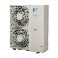
Secure the wiring in the order shown below.
1 Secure the ground wire to the shut-off valve attachment plate so
that it does not slide.
2 Secure the ground wire to the shut-off valve attachment plate
one more time along with the electric wiring and the inter-unit
wiring.
■ Lay the electrical wiring so that the front cover does not rise up
when doing wiring work and attach the front cover securely.
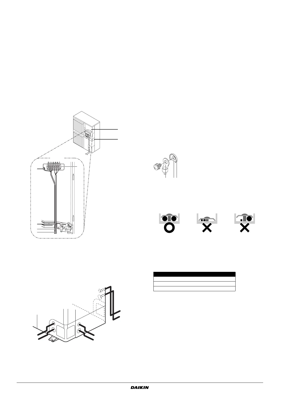
■ When cables are routed from the unit, a protection sleeve for the
conduits (PG-insertions) can be inserted at the knock-out hole.
(See figure 7)
When you do not use a wire conduit, be sure to protect the wires
with vinyl tubes to prevent the edge of the knock-out hole from
cutting the wires.
■ Follow the electric wiring diagram for electrical wiring works.
■ Form the wires and fix the cover firmly so that the cover may be
fit in properly.
Precautions on wiring of power supply and inter-unit
wiring
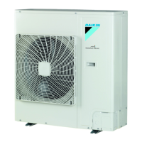
■ Use a round crimp-style terminal for connection to the power
supply terminal board. In case it cannot be used due to
unavoidable reasons, be sure to observe the following
instruction.
- Do not connect wires of different gauge to the same power
supply terminal. (Looseness in the connection may cause
overheating.)
- When connecting wires of the same gauge, connect them
according to the below figure.
■ Use the correct screwdriver to tighten the terminal screws.
Small screwdrivers can damage the screw head and prevent
appropriate tightening.
■ Over-tightening the terminal screws can damage the screws.
■ See the table below for tightening torques for the terminal
screws.
■ Refer to the installation manual attached to the indoor unit for
wiring of indoor units, etc.
■ Attach an earth leakage breaker and fuse to the power supply
line. (See figure 9)
1 Switch box
2 Stop valve mounting plate
3 Ground
4 Tie-wrap
5 Wiring between units
6 Power supply and ground wiring
1 Power supply wiring and earth wire
2 Wiring between unit
3
3
4
5
6
2
1
V3
1
2
1
2
1
2
1 Wire
2 Bush
3 Nut
4 Frame
5 Hose
A Inside
B Outside
Tightening torque (N•m)
M4 (X1M) 1.2~1.8
M5 (X1M) 2.0~3.0
M5 (EARTH) 3.0~4.0
I Pair
II Twin
III Tr iple
IV Double twin
M Master
S Slave
1 Earth leakage breaker
2 Fuse
3 Remote controller
123
1 Round pressure terminal
2 Cut out section
3 Cup washer