RZQS71~125B7V3B
Split System air conditioners
4PW32097-1A
Installation manual
6
Allowable pipe length and height difference
See the table below concerning lengths and heights. Refer to figures
2, 3, 4 and 5. Assume that the longest line in the figure corresponds
with the actual longest pipe, and the highest unit in the figure
corresponds with the actual highest unit.
Allowable pipe length
PRECAUTIONS ON REFRIGERANT PIPING
■ Do not allow anything other than the designated refrigerant to
get mixed into the freezing cycle, such as air, etc. If any
refrigerant gas leaks while working on the unit, ventilate the
room thoroughly right away.
■ Use R410A only when adding refrigerant
Installation tools:
Make sure to use installation tools (gauge manifold charge hose,
etc.) that are exclusively used for R410A installations to
withstand the pressure and to prevent foreign materials (e.g.
mineral oils and moisture) from mixing into the system.
Vacuum pump:
Use a 2-stage vacuum pump with a non-return valve
Make sure the pump oil does not flow oppositely into the system
while the pump is not working.
Use a vacuum pump which can evacuate to –100.7 kPa (5 Torr,
–755 mm Hg).
■ In order to prevent dirt, liquid or dust from entering the piping,
cure the piping with a pinch or taping.
Great caution is needed when passing copper tubes through
walls.
■ In case of simultaneous operating system
- Upward and downward piping should be performed at the
main piping line.
- Use branch piping kit (optional) for branching refrigerant
pipes.
Precautions to be taken. (For details, refer to the manual attached to
branch piping kit.)
- Install the branch pipes horizontally (with a maximum
inclination of 15°) or vertically.
- Length of branch pipe to the indoor unit should be as short as
possible.
-Try to keep lengths of both branch pipes to the indoor unit
equal.
REFRIGERANT PIPING
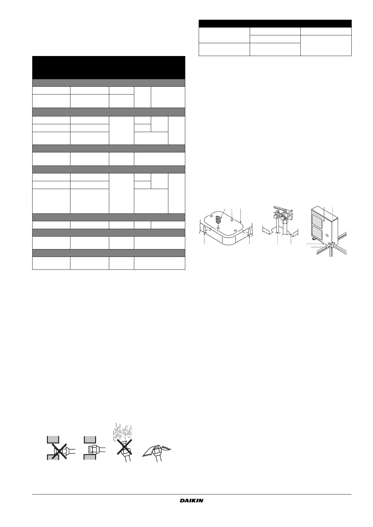
■ Field pipes can be installed in four directions.
Figure - Field pipes in four directions
■ Cutting out the two slits makes it possible to install as shown in
the figure "Field pipes in four directions".
(Use a metal saw to cut out the slits.)
■ To install the connecting pipe to the unit in a downward direction,
make a knockout hole by penetrating the center area around the
knockout hole using a
Ø6 mm drill. (See figure "Field pipes in
four directions".)
■ After knocking out the knock-out, it is recommended to apply
repair paint to the edge and the surrounding end surfaces to
prevent rusting.
Allowable pipe length
Liquid pipe
size
Model
71 100 125
Maximum total one-way piping length
Pair L1 standard
30 m
(40 m)
50 m (70 m)
•Twin and triple
• Double twin
• L1+L2
• L1+L2+L4
standard
Maximum allowable piping length
(a)
(a) Parenthesized figure represents the equivalent length.
Twin L1+L2+L3
—
30 m
50 m
50 m
Tr iple L1+L2+L3+L4 —
Double twin L1+L2+L3+L4+L5
+L6+L7
—
Maximum branch piping length
•Twin and triple
• Double twin
•L2
• L2+L4
— 20 m
Maximum difference between branch lengths
Twin L2–L3
—
10 m
10 m
10 m
Tr iple L2–L4 —
Double twin • L2–L3
• L4–L5
• L6–L7
•(L2+L4)–(L3+L7)
—
Maximum height between indoor and outdoor
All H1 — 15 m 30 m
Maximum height between indoors
Twin, triple and
double twin
H2
— 0.5 m
Chargeless length
All L1+L2+L3+L4+L5
+L6+L7
standard ≤30 m
Place Installation period Protection method
Outdoor unit
More than a month Pinch the pipe
Less than a month
Pinch or tape the pipe
Indoor unit
Regardless of the
period
1 Drill
2 Center area around knockout hole
3 Knockout hole
4 Slit
5 Connecting pipe
6 Bottom frame
7 Front plate
8 Pipe outlet plate
9 Screw front plate
10 Pipe outlet plate screw
A Forward
B Backward
C Sideways
D Downward
44
321
78
9
10
A
D
C
B
5 6