EasyManua.ls Logo

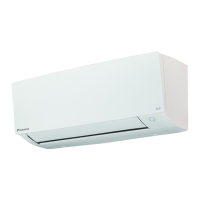
Daikin Siesta ATXN35MV1B7 User Manual

Daikin Siesta ATXN35MV1B7
156 pages
To Next Page IconTo Next Page
Page #1 background imageLoading...
Page #1 background image
DAIKIN
INSTALLATION
MANUAL
R410A SPLIT SERIES
<INVERTER>
MODELS
ATXN2SMV187
ATXN3SMV187
ATXNSOMV187
ATXN60MV187
ATXN2SNV18
ATXN3SNV18
ATXNSONV18
ATXN60NV18
ATXN20MV16
ATXN2SMV16
ATXN3SMV16
ATXNSOMV16
ATXN60MV16
ARXN2SMV187
ARXN3SMV187
ARXNSOMV187
ARXN60MV187
ARXN2SNV18
ARXN3SNV18
ARXNSONV18
ARXN60NV18
ARXN20MV16
ARXN2SMV16
ARXN3SMV16
ARXNSOMV16
ARXN60MV16
In
stallation Manual
R41
OA
Split Series
Manuale d'installazione
Serie Multiambienti
R41
OA
In
stallationsanleitung
Split-Baureihe
R41
OA
Manual de instalaci6n
Serie Split
R41
OA
Manuel d'installation
Serie split
R41
OA
Mo
ntaj ky
la
vuzlary
R41
OA
Split serisi
English
Italiano
Deutsch
Espanol
Franc;ais
Turkc;e
PYKOBO,QCTBO no MOHTa>K)'
Cepll1R
R410A
c
pa3,QeJlbHOIiI
YCTaHoBKoliI
PYCCKIiIM
~H[
(Applicable to cenified models only)
IM-5WMYJR-1113(4)-DAIKIN SIESTA
Part Number.: ROa019039397D
Question and Answer IconNeed help?

Do you have a question about the Daikin Siesta ATXN35MV1B7 and is the answer not in the manual?

Daikin Siesta ATXN35MV1B7 Specifications

General IconGeneral
BrandDaikin
ModelSiesta ATXN35MV1B7
CategoryAir Conditioner
LanguageEnglish

Summary

OUTLINE AND DIMENSIONS

Indoor Unit Dimensions

Detailed measurements and diagrams for the indoor unit.

Outdoor Unit Dimensions

Detailed measurements and diagrams for the outdoor unit.

SAFETY PRECAUTIONS

WARNING

Critical safety warnings for installation and maintenance personnel.

CAUTION

Important safety notes and precautions during installation.

IMPORTANT INFORMATION

Refrigerant Information

Details about the R410A refrigerant and its properties.

INSTALLATION PROCEDURES

Installation Diagrams

Visual guides for installing indoor and outdoor units.

Indoor Unit Installation

Step-by-step guide for installing the indoor unit.

Outdoor Unit Installation

Step-by-step guide for installing the outdoor unit.

Refrigerant Piping

Guidelines for refrigerant pipe length, works, and connections.

Electrical Wiring Connection

Diagrams and instructions for connecting electrical wiring.

Vacuuming and Charging

Procedures for system vacuuming and refrigerant charging.

OPERATING AND INDICATORS

Indicator Lights

Explanation of unit status and fault indicator lights.

Operating Range

Defines the operational temperature limits for cooling and heating.

MAINTENANCE AND TROUBLESHOOTING

Air Filter

Instructions for air filter maintenance and installation.

Service and Maintenance

Procedures for cleaning the indoor unit and air filter.

Troubleshooting

Common faults, causes, and recommended actions.

Related product manuals