
G
gonzalezmatthewAug 4, 2025
What to do if my Daikin VAM 350GJVE shows an overall alarm?
- KkathypittmanAug 4, 2025
If your Daikin Fan displays an overall alarm, you should take necessary measures by referring to the displayed error code.
What to do if my Daikin VAM 350GJVE shows an overall alarm?
If your Daikin Fan displays an overall alarm, you should take necessary measures by referring to the displayed error code.
What to do if my Daikin VAM 350GJVE Fan is showing an overall malfunction?
In case of an overall malfunction with your Daikin Fan, you should take necessary measures by referring to the displayed error code.
What to do if there is a LCD remote controller connection error on my Daikin Fan?
If you are experiencing an LCD remote controller connection error with your Daikin Fan, you should take necessary measures by referring to the displayed error code.
What should I do if there is a transmission error between the unit and centralized controller of my Daikin Fan?
If a transmission error occurs between the Daikin Fan unit and the centralized controller, you should take necessary measures by referring to the displayed error code.
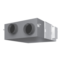
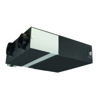
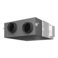
Details the fundamental structural components and design of the ventilation unit.
Provides a detailed explanation of each component and its function within the unit.
Outlines the technical specifications and performance data of the HRV units.
Presents detailed technical parameters including efficiency, dimensions, and operating conditions.
Covers the general operational aspects and system configurations for the HRV unit.
Explains how the HRV unit operates in different system configurations (independent, combined).
Details the operation of HRV units using a dedicated remote control for air conditioning.
Guides on operating the HRV unit with a VRV-system air conditioner remote controller.
Provides an overview of maintenance procedures for the HRV unit.
Explains how to clean and maintain the air filter of the HRV unit.
Details the procedure for cleaning and maintaining the heat exchange element.
Lists and describes the various control functions available for the HRV unit.
A comprehensive list of all control functions categorized by classification.
Provides detailed explanations for each individual control function of the HRV unit.
Illustrates the layout of switches on the main unit's printed circuit board.
Introduces the operational principles of the HRV unit's internal circuits.
Shows the overall circuit configuration diagram of the HRV unit's electrical system.
Explains the functions of various circuits and components within the HRV unit.
Provides guidance on diagnosing and resolving common issues and malfunctions.
Explains how to interpret error codes displayed on the remote controller.
Details the causes and troubleshooting steps for overall alarm conditions.
Addresses general malfunctions and their troubleshooting procedures.
Covers errors related to the indoor air temperature sensor.
Addresses issues caused by the outdoor air temperature sensor.
Explains errors related to the damper system and its associated alarms.
Further details on damper system errors, potentially in conjunction with other faults.
Troubleshooting specific issues with the dedicated LCD remote controller.
Diagnoses data transmission errors between the remote controller and the main unit.
Troubleshoots data transmission errors occurring solely with the LCD remote controller.
Addresses data transmission issues between master and slave remote controllers.
Guides on resolving errors related to field setting configurations.
Troubleshoots issues arising from duplicate central control addresses.
Covers troubleshooting steps for problems with the main unit's PCB assembly.
Further troubleshooting for the dedicated LCD remote controller, focusing on display issues.
Step-by-step instructions for performing checks on various components.
Details how to check and troubleshoot thermistor errors.
Explains how to check the power transformer for faults.
Guides on troubleshooting issues with the damper motor.
Provides additional information and explanations beyond the main sections.
Details procedures for field setting and service mode operations.
Explains the initial setup process using field setting modes.
Covers the operation and use of the service mode for unit management.
Further details on field setting procedures using the remote controller.
Provides reference information on the LCD display and operation panel features.
Crucial safety instructions and warnings for operating and handling the unit.
Important steps and checks to perform before starting the HRV unit.
Identifies and labels the key components of the HRV unit.
Explains the functions of buttons, displays, and indicators on the remote controllers.
Describes how the HRV unit integrates and operates within different system types.
Outlines the steps for operating the HRV unit in various modes.
Details how to operate the unit independently or as part of a combined system.
Guides on setting scheduled start and stop times for the HRV unit using the timer.
Explains the automatic heat purge function for energy conservation at night.
Procedures for maintenance that must be performed by qualified service personnel.
General troubleshooting steps for common operational problems.
Information regarding service, repairs, and warranty after the initial sale.
Contains supplementary technical information and diagrams.
Provides detailed wiring diagrams for different HRV unit models.
| Airflow Rate | 350 m³/h |
|---|---|
| ESP | 50 Pa |
| Voltage | 220-240 V |
| Frequency | 50/60 Hz |
| Sound Pressure Level | 28 dB(A) |
| Noise Level | 28 dB(A) |