Do you have a question about the Daikin VRV EMERION RXYQ-AATJA and is the answer not in the manual?
Essential safety precautions for repair work and general use.
Explanation of symbols used in the manual for warnings and notes.
Details of various outdoor and indoor unit model designations.
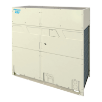
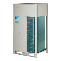
Visual identification of single and double outdoor units.
Information on connection ratios and allowable combinations of indoor/outdoor units.
Technical specifications for RXYQ-AATJA and RXYQ-AAYDA models.
Detailed piping diagrams for outdoor units with component identification.
Visual layout of key components within outdoor units for specific models.
Diagrams illustrating refrigerant flow during cooling, oil return, and defrost operations.
Lists indoor units compatible with wired and wireless remote controllers.
Detailed explanation of buttons and screen displays for the BRC1E73 remote controller.
Procedure for configuring primary and secondary remote controllers for a single indoor unit.
Steps to set addresses for receivers and wireless remote controllers for multi-room systems.
How to set group numbers for centralized control using operating remote controllers.
Accessing service data and various settings via the remote controller.
Overview of system operation logic, including stop, standby, and startup controls.
Explains normal operation parameters for compressor and fan motors, and expansion valves.
Details on high pressure, low pressure, discharge pipe, and inverter protection controls.
Explains functions like pump down, oil return, and defrost operations.
Detailed control logic for indoor units, including thermostat and swing flap operations.
Guide to configuring indoor unit functions using the remote controller.
Instructions for setting parameters via DIP switches and BS buttons on the outdoor unit PCB.
Procedures for verifying correct operation after installation and field settings.
Troubleshooting guide based on observed system symptoms and supposed causes.
Detailed breakdown of error codes, their descriptions, and troubleshooting steps.
Explanation of prediction codes and their corresponding possible causes and tech tips.
Procedures for checking specific components like sensors, valves, and PCB.
Electrical wiring diagrams for outdoor units, indoor units, and accessories.
Step-by-step instructions for removing the electrical component box.


