EasyManua.ls Logo

Daikin VRV IV+ Series User Manual

Daikin VRV IV+ Series
44 pages
To Next Page IconTo Next Page
Page #1 background imageLoading...
Page #1 background image
Installation and operation manual
VRV IV+ heat pump for high ambient temperatures
English
Installation and operation manual
VRV IV+ heat pump for high ambient temperatures
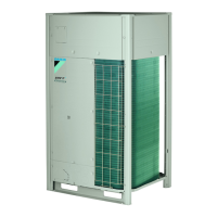
RXYTQ8U7YF
RXYTQ10U7YF
RXYTQ12U7YF
RXYTQ14U7YF
RXYTQ16U7YF

Questions and Answers:

Daikin VRV IV+ Series Specifications

General IconGeneral
SeriesVRV IV+
RefrigerantR-410A
Inverter TechnologyYes
Energy EfficiencyHigh
Operating Temperature Range (Cooling)-5°C to 46°C
Operating Temperature Range (Heating)-20°C to 15.5°C
Maximum Piping Length1000 m
TypeVariable Refrigerant Volume (VRV) Heat Pump
Capacity Range8 HP to 24 HP
Cooling Capacity Range22.4 kW to 61.5 kW
Heating Capacity Range25 kW - 150 kW
Noise Level (Outdoor Unit)55 dB(A) to 70 dB(A)
Power Supply380-415V, 3-phase, 50Hz
Maximum Height Difference50 m
Indoor Unit CompatibilityCassette, Duct, Wall Mounted
Coefficient of Performance (COP)Up to 4.5 (depending on model)

Summary

Installation and Operation Manual

VRV IV+ Heat Pump for High Ambient Temperatures

Manual title detailing the VRV IV+ heat pump for high ambient temperatures.

About the Documentation

About This Document

General information about the document structure, purpose, and audience.

User Safety Instructions

General Safety Precautions

Important safety guidelines for users to prevent harm and ensure proper operation.

Safe Operation Instructions

Specific instructions for operating the unit safely, covering electrical and physical hazards.

About the System

System Layout

Explains the overall system configuration and components, including indoor and outdoor units.

User Interface

Operation Range

Specifies the temperature and humidity limits for safe and effective system operation.

Operation

Operating the System

Details on how to turn on, operate, and manage the system based on unit and interface combinations.

Cooling, Heating, Fan-Only, and Automatic Operation

Explains how to select and perform different operating modes for the system.

Heating Operation Details

Information on heating operation, including defrost and hot start functions for optimal performance.

System Operation without Changeover Switch

Steps to operate the system using basic controls without a dedicated cool/heat changeover switch.

System Operation with Changeover Switch

Procedures for operating the system using a cool/heat changeover remote control switch.

Using the Dry Program

Functionality and usage of the dry program for humidity reduction with minimal temperature change.

Adjusting Air Flow Direction

Instructions on how to adjust the air flow direction using the unit's flap and settings.

Maintenance and Service

Refrigerant Information

Details on the refrigerant type, GWP, and safety precautions related to its handling.

After-Sales Service and Warranty

Information on warranty periods, service contracts, and how to request dealer assistance.

Recommended Maintenance and Inspection

Guidance on regular maintenance and inspection to ensure optimal unit performance and longevity.

Troubleshooting

Error Codes Overview

Explains how to interpret and address malfunction codes displayed by the system for diagnosis.

Non-Malfunction Symptoms

Lists common symptoms that are not actual malfunctions but normal system behavior.

Relocation

Disposal

About the Box Contents

About LOOP Program

Information about Daikin's environmental commitment and circular economy initiative for refrigerants.

Removing Outdoor Unit Accessories

Instructions on how to safely remove accessories from the outdoor unit before installation.

Units and Options

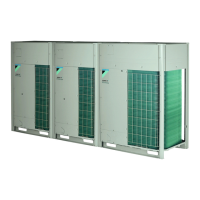
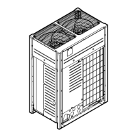
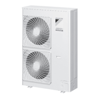
About the Outdoor Unit

Overview of the VRV IV heat pump outdoor unit, including its features and model lineup.

System Layout

Visual representation of the system components and their interconnections, emphasizing installation conditions.

Accessory Pipe Diameters

Table detailing the required diameters for gas and liquid pipes used as accessories.

Removing Transportation Stay

Step-by-step guide on how to remove the transportation stay from the compressor leg for safe operation.

Unit Installation

Preparing the Installation Site

Guidelines for preparing the installation site, including environmental and structural requirements.

Outdoor Unit Installation Site Requirements

Specific requirements for the outdoor unit installation location, including spacing and environmental factors.

Additional Site Requirements in Cold Climates

Precautions and requirements for installing the outdoor unit in low ambient temperatures with high humidity.

Opening the Unit

Instructions on how to safely open the outdoor unit for access to internal components and electrical parts.

Mounting the Outdoor Unit

Guidance on how to securely mount the outdoor unit on a stable base to prevent vibration and noise.

Piping Installation

Preparing Refrigerant Piping

Essential requirements for preparing refrigerant piping, focusing on cleanliness and material specifications for R410A.

Selecting Piping Size

Procedures for determining the correct sizes for gas and liquid refrigerant piping based on system capacity.

Selecting Refrigerant Branch Kits

Guidance on choosing the appropriate refrigerant branch kits based on outdoor unit capacity and indoor unit connections.

Multiple Outdoor Units: Possible Layouts

Illustrates various piping layouts for systems with multiple outdoor units, addressing oil retention risks.

Connecting Refrigerant Piping

Routing Refrigerant Piping

Instructions on how to route refrigerant piping, including side and front connection methods and knockout hole preparation.

Connecting Piping to Outdoor Unit

Steps for connecting field-installed piping to the outdoor unit, emphasizing the use of accessory pipes and insulation.

Connecting Multi Connection Piping Kit

Guidance on installing multi connection piping kits, ensuring proper orientation and joint placement.

Protecting Against Contamination

Methods for sealing piping and wiring intake holes to prevent contamination and entry of small animals.

Using Stop Valve and Service Port

Procedures for operating stop valves and handling service ports, including tightening torques and precautions.

Removing Spun Pipes

Instructions for safely removing spun pipes, including necessary precautions regarding gas and oil.

Checking Refrigerant Piping

About Checking Refrigerant Piping

Overview of refrigerant piping checks, including leak testing and vacuum drying procedures before powering the system.

General Guidelines for Checking Piping

General recommendations for efficient leak testing and vacuum drying, including equipment setup.

Checking Refrigerant Piping: Setup

Detailed setup instructions for performing leak tests and vacuum drying on the refrigerant piping system.

Charging Refrigerant

Precautions When Charging Refrigerant

Safety warnings and essential precautions to follow when charging the system with refrigerant, including personal protective equipment.

Performing a Leak Test

Step-by-step guide for conducting vacuum and pressure leak tests to ensure piping integrity.

Performing Vacuum Drying

Procedures for removing moisture from the system, essential for proper refrigerant charging and operation.

Insulating Refrigerant Piping

Instructions on how to properly insulate refrigerant piping to prevent condensation and ensure thermal efficiency.

About Charging Refrigerant

General guidance on the refrigerant charging process, including steps for manual charging and pre-charging.

Determining Additional Refrigerant Amount

Formula and tables to calculate the correct amount of additional refrigerant needed for the system.

Refrigerant Charging Flow Chart

A visual flow chart detailing the steps for pre-charging refrigerant, including overcharge handling.

To Charge Refrigerant

Detailed procedure for performing the refrigerant charging process, including pre-charging and manual charging steps.

Manual Refrigerant Charge Step 6

Specific instructions for manual refrigerant charging, including timing and stopping the process.

Error Codes During Refrigerant Charging

Lists error codes that may occur during charging and provides solutions for each.

Checks After Refrigerant Charging

Final checks to be performed after refrigerant charging to ensure the system is ready.

Electrical Installation

Safety Device Requirements

Specifies the required safety devices like fuses, circuit breakers, and earth leakage protectors for power supply.

Field Wiring Overview

General overview of field wiring, including power supply, transmission wiring, and communication systems.

Routing and Fixing Transmission Wiring

Instructions on how to route and secure the transmission wiring within the unit.

Connecting Transmission Wiring

Steps for connecting the transmission wiring between indoor and outdoor units.

Finishing Transmission Wiring

How to neatly finish the transmission wiring using tape and secure it properly.

Routing and Fixing Power Supply

Guidance on routing and securing the power supply wiring, ensuring clearance from other components.

Connecting Power Supply

Procedures for connecting the power supply to the unit, including earth wire usage and terminal connections.

Checking Compressor Insulation Resistance

Steps to measure and verify the insulation resistance of the compressor, especially after refrigerant accumulation.

Configuration

Making Field Settings

Instructions on how to make essential field settings for the outdoor unit and system configuration.

About Making Field Settings

Explains the purpose and process of making field settings via the master outdoor unit.

Field Setting Components

Identifies the location of 7-segment displays, buttons, and DIP switches used for field settings.

Accessing Field Setting Components

Steps to access the push buttons and displays on the PCB without opening the main electronic component box.

Accessing Mode 1 or 2

How to switch between default, mode 1 (monitoring), and mode 2 (field settings) using the BS1 button.

Using Mode 1

Instructions for using Mode 1 to set basic settings and monitor unit status, including navigation controls.

Using Mode 2

Procedures for using Mode 2 to set field settings for the outdoor unit and system, with detailed navigation steps.

Mode 1: Monitoring Settings

Explains the various monitoring parameters available in Mode 1, such as unit status and connected units.

Mode 2: Field Settings

Details on specific field settings available in Mode 2, including Cool/Heat selection and system combination settings.

Commissioning

Precautions When Commissioning

Important safety precautions to follow before and during the commissioning test run, especially regarding indoor units.

Checklist Before Commissioning

A checklist of essential items to verify after installation and before powering up the unit for commissioning.

About the Test Run

Overview of the test run procedure, its purpose, and what to check for, including potential malfunction codes.

Performing a Test Run

Step-by-step guide on how to perform the automatic system test run and interpret its results.

Correcting Abnormal Test Run Completion

Procedures for addressing and correcting abnormalities identified during the test run, including re-testing.

Hand-over to the User

Troubleshooting

Solving Problems Based on Error Codes

Guide to resolving issues by interpreting error codes displayed on the unit, including main and sub codes.

Error Codes Overview

A comprehensive list of error codes, their causes, and suggested solutions for troubleshooting.

Troubleshooting: Error Codes

Detailed listing of error codes, their causes, and recommended solutions for various system malfunctions.

Troubleshooting: Error Codes Continued

Further listing of error codes related to transmission, power supply, wiring, and unit combinations with their solutions.

Technical Data

Service Space: Outdoor Unit

Recommended clearances around the outdoor unit for adequate servicing, air inlet, and air outlet.

Outdoor Unit Piping Diagrams

Schematic diagrams illustrating the refrigerant piping for different outdoor unit models (RXYTQ8, RXYTQ10+12, RXYTQ14+16).

Outdoor Unit Wiring Diagram

Wiring diagrams for the outdoor unit, explaining symbols and connections for various components.

Wiring Diagram Symbols and Legends

Explanation of symbols, wire colours, and component legends used in the wiring diagrams for different HP models.

Wiring Diagram Components List

A comprehensive list of components, their abbreviations, and corresponding identifiers used in the wiring diagrams.

Disposal

Related product manuals