Do you have a question about the Daikin VRV IV-S RXTQ-TAVJU Series and is the answer not in the manual?
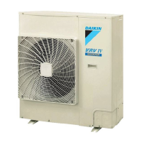
| Type | Heat Pump |
|---|---|
| Series | VRV IV-S |
| Model | RXTQ-TAVJU |
| Refrigerant | R-410A |
| Indoor Unit Type | Ceiling Cassette, Wall Mounted |
| Dimensions (Indoor Unit) | Varies by model |
| Dimensions (Outdoor Unit) | Varies by model |
| Operating Temperature Range (Cooling) | -5°C to 46°C |
| Power Supply | 208-230V, 60Hz |
| Maximum Height Difference | 50m |
Details the refrigerant circuit components for specific models.
Outlines the procedure for initial test operation after installation.
Details how to configure settings using the wired remote controller.
Lists initial checks and verification steps before starting service.
Provides common symptoms and their potential causes and countermeasures.
Sets the capacity class using an adaptor for specific outdoor units.
Steps for setting and performing refrigerant recovery operation.
Steps for performing vacuuming operation and setting the mode.
Procedure to stop the unit and initiate check operation.
Details troubleshooting for external protection device abnormalities (Error Code A0).
Details troubleshooting for indoor unit PCB abnormalities (Error Code A1).
Details troubleshooting for drain level control system abnormalities (Error Code A3).
Troubleshoots indoor fan motor abnormalities for FXDQ/FXHQ models (Error Code A6).
Troubleshoots indoor fan motor abnormalities for FXMQ models (Error Code A6).
Troubleshoots transmission errors between indoor unit and fan PCBs (Error Code C1).
Details troubleshooting for thermistor abnormalities (Error Codes C4, C5, C9, CA).
Troubleshoots combination errors between indoor unit and fan PCBs (Error Code C6).
Details troubleshooting for remote sensor abnormalities (Error Code C9).
Details troubleshooting for infrared presence/floor sensor errors (Error Code CE).
Troubleshoots humidity sensor system abnormalities (Error Code CC).
Details troubleshooting for outdoor main PCB abnormalities (Error Code E1).
Troubleshoots errors related to the activation of the high pressure switch (Error Code E3).
Troubleshoots errors related to low pressure sensor activation (Error Code E4).
Details troubleshooting for inverter compressor motor lock (Error Code E5).
Troubleshoots outdoor fan motor abnormalities (Error Code E7).
Troubleshoots electronic expansion valve coil issues and dust clogging (Error Code A9).
Details troubleshooting for discharge pipe temperature abnormalities (Error Code F3).
Troubleshoots errors related to refrigerant overcharging (Error Code F6).
Details troubleshooting for various thermistor abnormalities (Error Codes H9, J3, J5, J6, J7, J9).
Troubleshoots high pressure sensor abnormalities (Error Code JA).
Details troubleshooting for low pressure sensor abnormalities (Error Code JC).
Troubleshoots abnormalities related to the inverter compressor PCB (Error Code L1).
Details troubleshooting for radiation fin temperature rise (Error Code L4).
Troubleshoots instantaneous overcurrent in the inverter compressor (Error Code L5).
Details troubleshooting for inverter compressor overcurrent (Error Code L8).
Troubleshoots inverter compressor startup abnormalities (Error Code L9).
Troubleshoots transmission errors between microcomputers on the outdoor main PCB (Error Code LC).