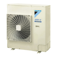
Do you have a question about the Daikin VRV II RXYQ5MATL and is the answer not in the manual?
General safety warnings and precautions to be observed before, during, and after repair work.
Specific safety warnings related to electrical shock, refrigerant handling, and component discharge.
Safety precautions to be followed after completing repair work, including tool usage and installation.
Control to prevent protection activation due to abnormal high pressure and protect compressors.
Control to prevent protection activation due to abnormal high pressure and protect compressors.
Control to protect compressors against transient decrease of low pressure.
Control to protect compressor internal temperature against discharge pipe temperature issues.
Controls to prevent tripping due to inverter overcurrent or fin temperature increase.
Control to prevent compressor heating due to overcurrent from STD compressor failures.
Step-by-step guide for conducting the initial test operation after installation.
Guides users through troubleshooting common system symptoms and their potential causes and countermeasures.
Explains how to select modes like inspection, test operation, local setting, and service mode using the remote.
Explains how to select modes like inspection, test operation, local setting, and service mode using the remote.
Troubleshooting steps for 'A0' error, indicating an external protection device issue.
Troubleshooting steps for 'A0' error, indicating an external protection device issue.
Troubleshooting steps for 'A1' error, indicating a defect in the indoor unit PC board.
Troubleshooting steps for 'A3' error, related to drain level control system malfunction.
Troubleshooting steps for 'A6' error, indicating fan motor lock or overload.
Troubleshooting steps for 'E1' error, indicating a defect in the outdoor unit PC board.
Troubleshooting steps for 'E3' error, indicating actuation of the high pressure switch.
Troubleshooting steps for 'E4' error, indicating actuation of the low pressure sensor.
Troubleshooting steps for 'E5' error, indicating compressor motor lock.
Troubleshooting steps for 'E6' error, indicating STD compressor motor overcurrent or lock.
Troubleshooting steps for 'E7' error, indicating malfunction of the outdoor unit fan motor.
Troubleshooting steps for 'F3' error, indicating abnormal discharge pipe temperature.
Troubleshooting steps for 'F6' error, indicating refrigerant overcharge.
Troubleshooting steps for 'J2' error, indicating a current sensor malfunction.
Troubleshooting steps for 'J3' error, indicating malfunction of the discharge pipe thermistor.
Troubleshooting steps for 'J5' error, indicating malfunction of the suction pipe thermistor.
Troubleshooting steps for 'J6' error, indicating malfunction of the heat exchanger deicer thermistor.
Troubleshooting steps for 'J7' error, indicating malfunction of the receiver outlet liquid pipe thermistor.
Troubleshooting steps for 'J9' error, indicating malfunction of the subcooling heat exchanger gas pipe thermistor.
Troubleshooting steps for 'JA' error, indicating malfunction of the high pressure sensor.
Troubleshooting steps for 'JC' error, indicating malfunction of the low pressure sensor.
Troubleshooting steps for 'L4' error, indicating inverter radiating fin temperature rise.
Troubleshooting steps for 'L5' error, indicating an inverter compressor abnormality.
Troubleshooting steps for 'L8' error, indicating an inverter current abnormality.
Troubleshooting steps for 'L9' error, indicating an inverter startup error.
Troubleshooting steps for 'LC' error, indicating transmission malfunction between inverter and control PC board.
Troubleshooting steps for 'P1' error, indicating inverter over-ripple protection.
Troubleshooting steps for 'P4' error, indicating malfunction of inverter radiating fin temperature rise sensor.
Troubleshooting steps for 'U0' error, indicating low pressure drop due to refrigerant shortage or EEV failure.
Troubleshooting steps for 'U1' error, indicating reverse or open phase in power supply.
Troubleshooting steps for 'U2' error, indicating insufficient power supply.
Troubleshooting steps for 'U3' error, indicating check operation was not executed.
Troubleshooting steps for 'U4' error, indicating transmission malfunction between indoor units.
Troubleshooting steps for 'U5' error, indicating transmission malfunction between remote controller and indoor unit.
Troubleshooting steps for 'U7' error, indicating transmission malfunction between outdoor units.
Troubleshooting steps for 'U8' error, indicating transmission malfunction between main and sub remote controllers.
Troubleshooting steps for 'U9' error, indicating transmission malfunction within the same system.
Troubleshooting steps for 'UA' error, indicating improper unit or controller combination.
Troubleshooting steps for 'UC' error, indicating address duplication in centralized control.
Troubleshooting steps for 'M1' error, indicating a defect in the central remote controller PC board.
Troubleshooting steps for 'UE' error, indicating transmission malfunction between centralized controller and indoor unit.
Troubleshooting steps for 'M1' error, indicating a defect in the schedule timer PC board.
Troubleshooting steps for 'M8' error, indicating transmission malfunction between optional controllers.
