Do you have a question about the Daikin VRV II RXYQ8MY1B and is the answer not in the manual?
| Model | RXYQ8MY1B |
|---|---|
| Category | Heat Pump |
| Type | VRV II |
| Cooling Capacity | 22.4 kW |
| Heating Capacity | 25.0 kW |
| Refrigerant | R410A |
| Operating Temperature (Heating) | -20 to 15.5°C |
| Power Supply | 380-415V, 50Hz |
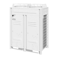
| Dimensions (Outdoor Unit) | 1680 x 930 x 765 mm |
| Operating Temperature (Cooling) | -5°C to 46°C |
| Indoor Unit Compatibility | Compatible with a wide range of Daikin indoor units |
Lists model names for various indoor and outdoor unit types, including capacity and power supply.
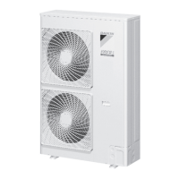
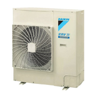
Outlines detailed technical specifications for outdoor units.
Provides detailed specifications for outdoor units, including cooling capacity, dimensions, and components.
Explains the refrigerant circuit for different RXYQ models, including components and their functions.
Details the refrigerant circuit components and their functions for RXYQ5M models.
Outlines the refrigerant circuit for RXYQ8, 10, and 12M models, specifying components and functions.
Describes the refrigerant circuit for RXYQ14 and 16M models, detailing components and their roles.
Illustrates refrigerant flow during different operation modes like cooling and heating.
Explains the actuator operations for normal cooling and heating modes, including remarks.
Describes various protection controls like high and low pressure protection.
Details the high pressure protection control to prevent compressor damage from abnormal pressure.
Explains the low pressure protection control to safeguard compressors from pressure drops.
Outlines protection against compressor internal temperature rise due to discharge pipe issues.
Describes inverter current and fin temperature protection to prevent tripping.
Explains the control to prevent abnormal heating due to STD compressor overload.
Explains how to perform emergency operation when a compressor or outdoor unit fails.
Outlines the procedures and general information for conducting initial test operations.
Provides a step-by-step procedure for initial test operations after installation, including checks.
Details how to perform field settings using the remote controller or outdoor unit settings.
Explains how to change indoor unit functions using the wired or wireless remote controller.
Describes how to make field settings using dip switches on the outdoor unit's PC board.
Covers troubleshooting methods using the remote controller, including self-diagnosis functions.
Describes how to perform self-diagnosis using a wired remote controller to identify malfunctions.
Explains the self-diagnosis procedure using a wireless remote controller for malfunction identification.
Explains the self-diagnosis function of the remote controller to identify malfunction contents and locations.
Lists common malfunction codes displayed on the remote controller and their troubleshooting steps.
Explains the "A0" error code indicating an external protection device issue and its troubleshooting.
Details the "A1" error code for PC board defects and the steps to resolve it.
Covers the "A3" error code related to drain level control system malfunctions and troubleshooting.
Explains the "A6" error code for fan motor lock or overload and its resolution.
Explains the "C4" error code related to heat exchanger thermistor malfunctions and troubleshooting.
Covers the "C5" error code for gas pipe thermistor malfunctions and its resolution.
Details the "C9" error code for suction air thermistor malfunctions and troubleshooting.
Covers the "E1" error code for outdoor unit PC board defects and troubleshooting.
Details the "E3" error code related to high pressure switch actuation and its resolution.
Explains the "E4" error code for low pressure sensor actuation and troubleshooting steps.
Covers the "E5" error code for compressor motor lock and its resolution.
Details the "E6" error code for compressor motor overcurrent or lock and troubleshooting.
Explains the "E7" error code for outdoor unit fan motor malfunctions and its resolution.
Covers the "E9" error code for electronic expansion valve moving part issues and troubleshooting.
Details the "F3" error code for abnormal discharge pipe temperature and its resolution.
Explains the "F6" error code for refrigerant overcharge and troubleshooting.
Details the "H9" error code for outdoor air thermistor malfunctions and troubleshooting.
Explains the "J2" error code for current sensor malfunctions and its resolution.
Provides a step-by-step guide for replacing the INV compressor in VRV II systems.
Details the specific steps and precautions for replacing the INV compressor.
Explains the procedure for replacing inverter power transistors and diode modules.
Outlines general precautions for handling the new R410 refrigerant.