a: φ15.9 × 30m
b: φ15.9 ×10m
c: φ9.5 × 20m
d: φ9.5 × 20m
e: φ9.5 × 20m
f : φ9.5 × 20m
g: φ9.5 × 20m
h: φ9.5 × 20m
i : φ9.5 × 10m
j : φ6.4 × 10m
k: φ6.4 × 10m
r: φ9.5 × 1m
s: φ9.5 × 1m
t : φ9.5 × 1m
u: φ12.7 × 3m
R= + +
+
ua, b c~i, r~t j, k
5.1 kg
×0.26
kg/m
×0.18
kg/m
Total length (m)
of liquid piping
size at φ12.7
×0.12
kg/m
×
0.022
kg/m
Example for refrigerant branch using REFNET joint and REFNET header
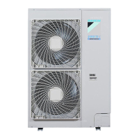
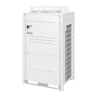
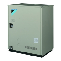
RQCYQ540PY1
116%
+
×
0.059
kg/m
(A: The ratio of total
capacity index of
connectable indoor
units to outdoor
capacity index (%))
In case the outdoor unit is
RQCYQ540PY1 type and the
piping lengths are as at right
Total capacity of indoor unit: 116%
RQYQ140
RQYQ180
RQCYQ280
RQCYQ360
RQCYQ460
RQCYQ500
RQCYQ540
2.4 kg
2.4 kg
6.8 kg
6.8 kg
11.2 kg
11.2 kg
11.2 kg
A ≤ 100%
A > 100%
0 kg
0.5 kg
How to calculate the additional refrigerant to
be charged
Additional refrigerant to be charged R (kg)
(R should be rounded off in units of 0.1kg.)
Total length (m)
of liquid piping
size at φ19.1
Total length (m)
of liquid piping
size at φ15.9
Total length (m)
of liquid piping
size at φ6.4
Total length (m)
of liquid piping
size at φ9.5
∗Note 1
When the equivalent pipe length between outdoor unit multi connection piping kit and indoor units is 90m or more, the size of main pipes (both gas-side and liquid-side) must be increased to the
following table.
Depending on the length of the piping, the capacity may drop, but even in such case it is able to increase the size of main pipes.
(Refer to figure 10.1)
1. Outdoor unit
2. Main pipes
3. Increase
4. The first refrigerant branch kit
5. Indoor unit
R= ( 40×0.18 + 3×0.12 + 1.33×0.059 + 20×0.022 ) 11.2 + 0.5 = 5.147
Piping size (O.D.)
φ15.9
à
φ19.1
φ19.1
à
φ22.2
φ22.2
à
φ25.4
φ25.4
à
φ28.6
φ28.6
à
φ34.9
φ9.5
à
Not increased
φ9.5
à
Not increased
φ9.5
à
φ12.7
φ12.7
à
φ15.9
φ15.9
à
φ19.1
Gas pipe
Liquid pipe
RQYQ140
RQYQ180
RQCYQ280
RQCYQ360
RQCYQ460
RQCYQ500, 540
Model name of
outdoor unit system

 Loading...


