23
ENGLISH
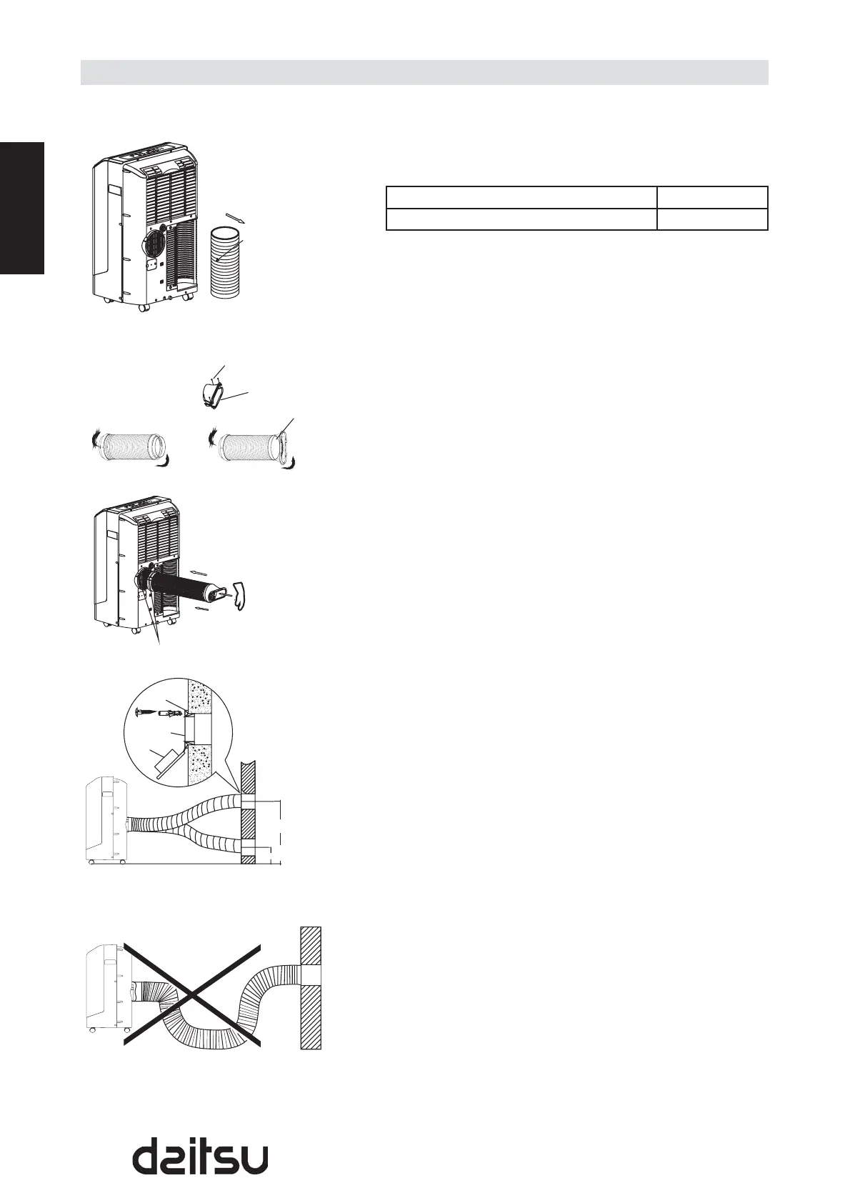
The exhaust hose and adaptor must be installed or removed
in accordance with the usage mode.
COOL mode Install
FAN or DEHUMIDIIFY mode Remove
For the fi rst time to use the machine, take the exhaust •
hose out as shown in Fig.18.
1. Install the adaptor B and adaptor I onto the exhaust hose
as shown in Fig.19a or Fig.19b. Refer to the previous
pages for window kit installation.
2. Place the Exhaust hose over against the air outlet
opening hook and fl at the other end (See Fig.20) for
quick installation.
Note:
Extend the both ends of the exhaust hose to a length of
30~50mm before install the adaptor B and adaptor I onto the
exhaust hose.
The exhaust hose can be installed into the wall
(Not applicable to the units without adaptor A, expansion
plugs and wooden screws of Accessories )
1. Prepare a hole in the wall. Install the wall Exhaust
adaptor A onto the wall (outside) by using 4 expansion
plugs and wooden screws, be sure to fi x thoroughly. (See
Fig.21).
2. Attach the Exhaust hose to wall Exhaust adaptor A.
Note:
Cover the hole using the adaptor cap when not in use.
The exhaust hose can be compressed or extended •
moderately according to the installation requirement, but
it is desirable to keep the hose length to a minimum.
IMPORTANT:
DO NOT OVER BEND THE EXHAUST HOSE (SEE Fig.22)
.
Exhaust hose installation
Expansion
plug position
Fig. 19a Fig. 19b
Fig. 18
Fig. 21
Fig. 22
Adaptor A
Adaptor cap
max 120 CM
min 30 CM
Fig. 20
Exhaust hose
Hook
Push in
Flat mouth
Use the screws to install
the fl at mouth
Flat mouth