Do you have a question about the Daiwa CNW-518 and is the answer not in the manual?
Covers frequency coverage, impedance, SWR sensitivity, measurement range, and tolerance for the SWR/Power meter.
Details frequency bands, impedance matching, power ratings, and insertion loss for the antenna tuner circuit.
Includes input/output connectors, physical dimensions, and net weight of the antenna tuner unit.
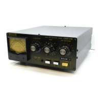
Describes the cross-needle meter for SWR/power and the LEDs indicating the selected power range.
Explains controls like Power Range Selector, Antenna Selector, Tuner Switch, TR Matching, and Band change-over.
Details the tuning knobs for the input (VC-1) and output (VC-2) capacitors for impedance matching.
Specifies connections for antennas, dummy loads, transmitters, and the essential earth ground terminal.
Identifies the DC socket used for powering the unit's indicator LEDs.
Outlines connection requirements, frequency limits, and switch settings for independent SWR/power meter use.
Details how to perform measurements for forward, reflected, and effective radiated power using the meter.
Covers continuity of connections and correct band selection for effective antenna tuning operations.
Provides steps to adjust tuning knobs for achieving the best SWR and maximizing transmitter output power.
Warns against critical actions like changing switches during transmission or using excessive power.
Explains the function of indicator LEDs and offers advice for troubleshooting unresolvable SWR problems.