MAN 650312 rev. E
QUICK START GUIDE
DAKOTA DIGITAL VFD SERIES III GAUGE SYSTEM
This guide is designed to get you up and running quickly with the minimal amount of options installed. It shows
a typical and abbreviated wiring diagram as well as how to set up your speedometer, tachometer, and fuel
sensor. A detailed description of all the wiring and connections can be found in the full instruction manual.
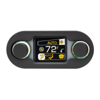
Mount the display panel into your dash. (see mounting instructions or manual)
Install the supplied senders. (see sensor pack manual)
Mount and wire the control box. (see diagram on this sheet or see manual)
Setup the control box by selecting fuel sensor and programming speed.
TACH
POWER
GROUND
WARN
DIM (+)
SPD +
SPD SND
SPD -
SPD OUT
SW2 (-)
SW1 (-)
ADJ SND
ADJ -
WTR SND
WTR -
OIL +
OIL SND
OIL -
RESERVED
(SEE MANUAL)
FUEL SND
FUEL -
WAIT (+)
CRUISE (-)
GEAR (1 WIRE)
4x4 (-)
RIGHT (+)
LEFT (+)
HIGH (+)
BRAKE (-)
CHECK ENG (-)
SERIES III
VFD CONTROL BOX
RIBBON CABLE
AUX.
I/O
DISPLAY
STRIPE
www.dakotadigital.com
techsupport@dakotadigital.com
605-332-6513
PULSE
GENERATOR
EXSISTING
FUEL LEVEL
SENSOR
RIBBON CABLE
DISPLAY PANEL
STATUS LED
+12V KEY POWER
ECU/ECM
Speed Output
Quick Start Wiring Diagram
This drawing is a quick overview of the basic
wiring for your new Dakota Digital system. Once
completed all the basic functions should operate;
speed, tachometer, fuel level, voltmeter, water
temp, and oil pressure.
For further wiring assistance please read the
remainder of the manual. Each function is
described in detail along with some of the
auxiliary inputs that include turn signal indicators,
high beam indicator, check engine, etc.
RED
WHITE
BLACK
BLUE or RED
BROWN or BLACK
RED
WHITE
BLACK
Additional ground wire to fuel
sensor body or mounting screw.
+12V KEY ON POWER
(fused 5 - 20 AMP max)
Connect to main
chassis ground
PRESSURE SENSOR
SEN-03-8
0-100 PSI
TEMP SENSOR
SEN-04-5
100-300 F
MOMENTARY SW2
MOMENTARY SW1
Ignition Coil
(negative side)
- +
ECU/ECM
or Ignition Box
(tach output)
SPEED SENSOR
SEN-01-5
16k PPM
Set up the control box to match your vehicle. The tachometer must be set to match the number of engine
cylinders and the fuel gauge must be set to match your fuel sender resistance curve or the instrument system will not
display correctly. The control box can read seven common fuel level sender resistance values. If your sender is not
listed, the system can be programmed to a custom sender (see full manual for details).
GM 0-30 ohm (mid 60’s-earlier)
GM 0-90 ohm (mid 60’s-late 90’s)
GM 40-250 ohm (late 90’s-later)
GM 90-0 ohm (63-67 Corvette)
FORD 73-10 ohm (earlier -late 80’s)
FORD 20-150 ohm (late 80’s-later)
***** IMPORTANT NOTE! *****
This control box has an odometer preset option that is only available one time within the first 100 miles
(160km) of operation. See “ODOMETER PRESET MENU” in main instruction manual for details.