EasyManua.ls Logo

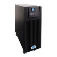
Dale Power Solutions E200 Series User Manual

Dale Power Solutions E200 Series
36 pages
To Next Page IconTo Next Page
Page #1 background imageLoading...
Page #1 background image
Dale Power Solutions Ltd
Salter Road, Eastfield Industrial Estate, Scarborough, North Yorkshire, YO11 3DU, UK
info@dalepowersolutions.com | www.dalepowersolutions.com | +44 (0) 1723 583511
S5264FU02 Rev 3
Dale Power Solutions Ltd
User Manual
E200 Series UPS
E206(E)
E2010(E)

Questions and Answers:

Dale Power Solutions E200 Series Specifications

General IconGeneral
BrandDale Power Solutions
ModelE200 Series
CategoryUPS
LanguageEnglish

Summary

Safety

EMC

Product for commercial/industrial use, C2 UPS, potential for radio interference.

Warning Symbols

Safety symbols and their meanings for installation, operation, and maintenance.

Product Description

Applications

Provides reliable AC backup power for computer centres, network management, etc.

Product Range

Lists available E200 series models and their battery configurations (internal/external).

System Block Diagram

Features

Highlights sine-wave output, DSP technology, LCD panel, network management, and hot-plug bypass.

Installation

Siting Considerations

Guidelines for UPS placement, temperature, ventilation, and clearance requirements.

Wiring Considerations

Instructions for safe electrical connections, circuit breakers, and cable sizing.

Operation from Generator

Circuit Breaker and Cable Sizes

Unpacking the UPS

Rear Panel Layout

Wiring the UPS

Connecting to the System

Detailed steps for connecting input, output, and battery cables to the UPS.

Wiring Units in Parallel

Connecting Multiple Units

Procedure for parallel operation, including bypass and CAN bus connections.

Operation

Working Modes Overview

Details the four operating modes: On-Line, Bypass, Battery, and ECO modes.

Before Switch On

Switching on the UPS

Switching off the UPS

Swapping out a UPS on a Live System

Front Panel Controls and Indicators

Navigating the System Menu

Figure Menu Items

Displays UPS operating information such as voltage, frequency, and load percentage.

Status Menu Items

Provides UPS system status, alarms, fault information, and rate power data.

User Set Menu Items

User-configurable settings like backlight timeout and brightness.

System Set Menu Items

System parameters including operating mode, voltage, and frequency settings.

Parallel Set Menu Items

Settings related to parallel operation, such as ID and redundancy mode.

Battery Set Menu Items

Battery settings like End of Discharge voltage and boost charge levels.

Revise Set Menu Items

Cautionary section for calibration settings; advised not to adjust without expertise.

Command Menu Items

Options for performing battery tests and setting turn-on/off delay times.

LCD Display Messages

Maintenance

Fan and Battery Maintenance

Covers fan operation, battery types, life maximization, and external battery replacement.

UPS Status and Function Checks

Procedures for visual checks, status monitoring, and periodic functional testing.

Troubleshooting

Appendix 1 Signals Options

RS232 Serial Port

Using the RS232 port for monitoring UPS status, alarms, and running parameters.

Contact Closure

Utilizing the DB9 socket for basic monitoring and control via dry contacts.

SNMP Card

Advanced monitoring and control via a network cable using an optional SNMP card.

Relay Card

Advanced monitoring via dry contacts and opto-coupled input with an optional relay card.

Appendix 2 Parallel Board Signals

LBS Load Bus Synchronisation

Synchronizing the output of two separate parallel UPS systems using LBS connectors.

Dry Contact Relay Signals

Wiring details for dry contact signals, including pinouts and descriptions.

Appendix 3 Specifications

Electrical Specifications

Detailed electrical parameters including input, battery, and output specifications.

Mechanical Specifications

Physical dimensions, net weight, colour, display type, and ingress protection.

Appendix 4 Optional Equipment

Lists available optional hardware components for the UPS units.

Appendix 5 UPS Alarm Tables

Related product manuals