FRONT AND REAR WING SIDEPLATES TABLE 22
• Front flap angle is measured on top of the flap front-end and inside the Gurney ‘corner’.
• Correspondence between holes and incidence angle is just indicative, because wing angle
is also a function of the front and rear ride heights.
• Machined side-plates allow 1 degree step adjustment.
FRONT
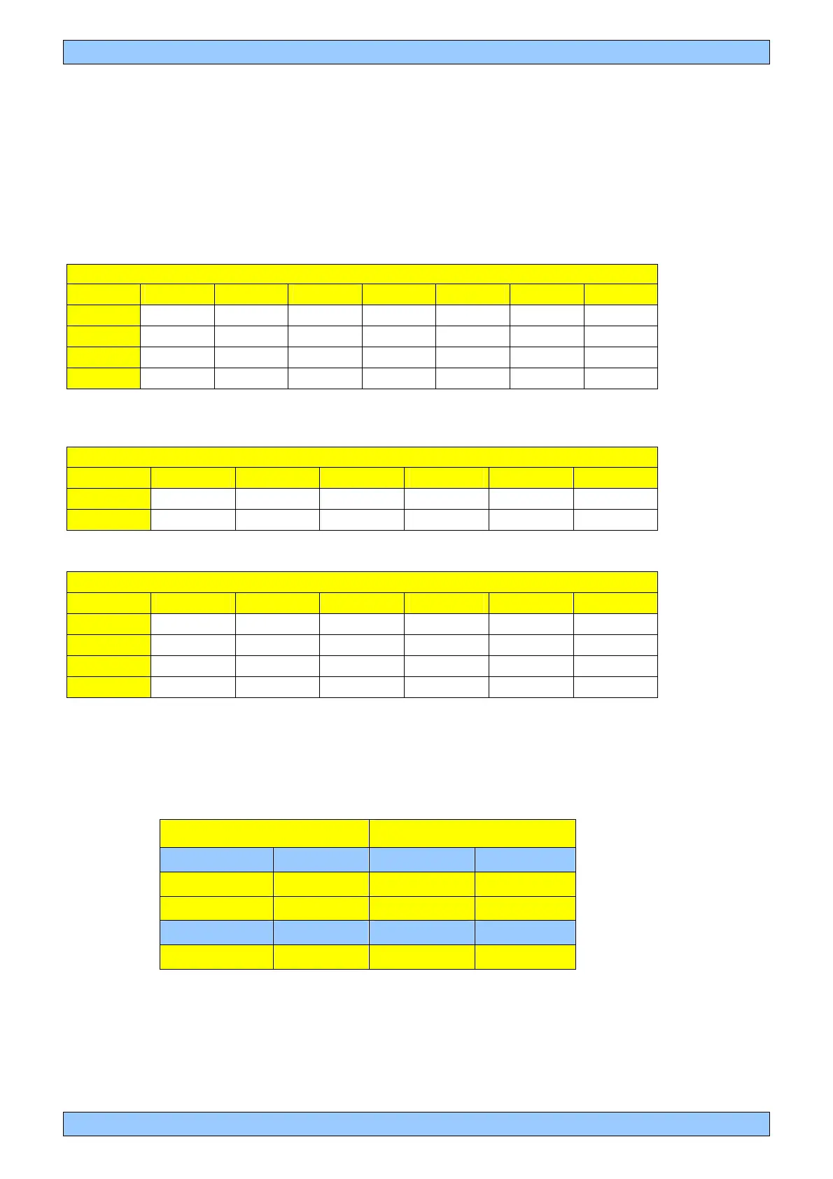
FRONT FLAP (MF & SF)
A B C D E F G
1 10° 11° 12° 13° 14° 15° 16°
2 17° 18° 19° 20° 21° 22° 23°
3 24° 25° 26° 27° 28° 29° 30°
4 31° 32° 33° 34° 35° 36° 37°
REAR
REAR TOP LDF
A B C D E F
1 0° 1° 2° 3° 4° 5°
2 6° 7° 8° 9° 10° 11°
MDF & HDF
A B C D E F
1 2° 3° 4° 5° 6° 7°
2 8° 9° 10° 11° 12° 13°
3 14° 15° 16° 17° 18° 19°
4 20° 21° 22° 23° 24° 25°
The following gives the F304 HDF rear wing incidence to achieve the same
level of down-force as the F303 HDF/UHDF rear wing configuration.
F304 F303
LOWER 7° 7° LOWER
HDF 12° 17° HDF
HDF 16° 21° HDF
LOWER 15° 15° LOWER
HDF 23° - UHDF
23 POLAR DIAGRAM


 To Next Page