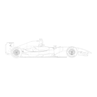
AERODYNAMIC INFORMATION 24
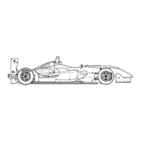
• Front wing main-plane and rear lower wing are set relative to the chassis reference
plane.
• The optimum setting for the front main-plane is -0.5° (minus 0.5°). Any chassis rake
angle will alter this setting.
• Front flap inclination is intended to be the angle, relative to the chassis reference plane,
measured on top of the flap front and inside the Gurney ‘corner’.
• Rear top wing assembly inclination is intended to be the angle, relative to the chassis
reference plane, measured between the front of the flap, on top and the rearmost
trailing edge. Any chassis rake will alter this setting.
• Front and rear ride height settings are fundamental to the aerodynamic balance and
ultimate performance of the car. Pay attention to the changes between static setting and
the dynamic values on the track.
MINIMUM SUGGESTED MAXIMUM SUGGESTED
DOWNFORCE CFG
HOLE INCIDENCE HOLE INCIDENCE
FRONT MF FLAP A1 10° G4 37°
FRONT SF FLAP A1 10° D4 34°
REAR TOP MDF WING A1 2° D4 23°
REAR TOP HDF WING A1 2° D4 23°
REAR LOWER cfg. 1-4 0° 7°
REAR LOWER cfg. 5-11 7° 16°
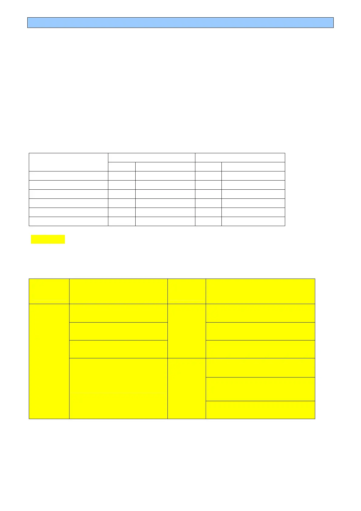
BALANCE
HOW TO BALANCE 1° FRONT FLAP VARIATION BY CHANGING THE REAR WING,
REAR RIDE HEIGHT OR FRONT RIDE HEIGHT?
Front
flap type
Rear top: MDF
Front
flap type
Rear top: HDF
0.7 holes
RR top
0.5 holes
RR top
1.3mm lower
RR height
1.4mm lower
RR height
0.6mm higher
FR height
MF
0.7mm higher
FR height
0.75 holes
RR top
2.5mm lower
RR height
MF
SF
1.3mm higher
FR height
MF: MEDIUM FLAP; SF: STANDARD FLAP


 To Next Page
 Loading...