EKC 316A Instructions RI8HA852 © Danfoss 04/2009 7
Start of controller
When the electric wires have been connected to the controller,
the following points have to be attended to before the regulation
starts:
1. Switch off the external ON/OFF switch that starts and stops the
regulation.
2. Follow the menu survey and set the various parameters to the
required values.
3. Switch on the external switch, and regulation will start.
4. Follow the actual room temperature or superheat on the
display.
If the superheating fluctuates
When the refrigerating system has been made to work steadily,
the controller’s factory-set control parameters should in most
cases provide a stable and relatively fast regulating system.
If the system however fluctuates this may be due to the fact that
too low superheat parameters have been selected:
If adaptive superheat has been selected:
Adjust: n09, n10 and n18.
If load-defined superheat has been selected:
Adjust: n09, n10 and n22.
Alternatively it may be due to the fact that the set regulation
parameters are not optimal.
If the time of oscillation is longer than the integration time:
(T
p
> T
n
, (T
n
is, say, 240 seconds))
1. Increase T
n
to 1.2 times T
p
2. Wait until the system is in balance again
3. If there is still oscillation, reduce K
p
by, say, 20%
4. Wait until the system is in balance
5. If it continues to oscillate, repeat 3 and 4
If the time of oscillation is shorter than the integration time:
(T
p
< T
n
, (T
n
is, say, 240 seconds))
1. Reduce K
p
by, say, 20% of the scale reading
2. Wait until the system is in balance
3. If it continues to oscillate, repeat 1 and 2.
Check that the ETS valve closes when the
supply voltage to the controller is interrupted
This control is performed if the controller is connected to battery
backup.
The battery will make the step motor move to the end stop and
thus close the valve.
The control may be omitted if a solenoid valve is mounted and
connected via terminals 9-10.
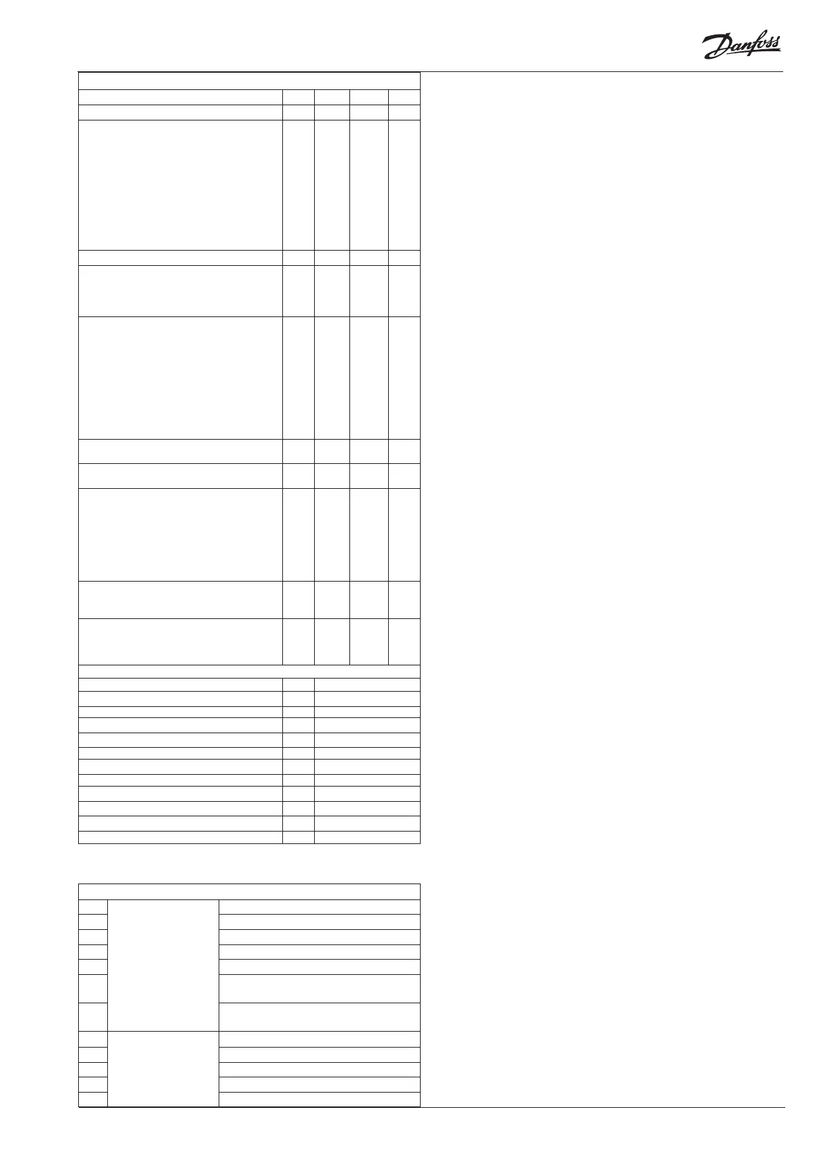
The controller can give the following messages:
E1
Error message
Fault in controller
E15 Cut-out S2 sensor
E16 Shortcircuited S2 sensor
E17 Cut-out S3 sensor
E18 Shortcircuited S3 sensor
E19
The input signal on terminals 16-17 is outside
the range.
E20
The input signal on terminals 14-15 is outside
the range (P0 signal)
A1
Alarm message
High-temperature alarm
A2 Low-temperature alarm
A11 No refrigerant has been selected
A43 Check the supply voltage to the step motor
A44 Battery alarm (no voltage or too low voltage)
Miscellaneous
Controller’s address o03*** 0 119 0
ON/OFF switch (service-pin message) o04*** - - -
Define input signal on the analoge input AIA:
0: no signal,
1: Temperature setpoint. 0-20 mA
2: Temperature setpoint. 4-20 mA
3: Displacement of superheat reference. 0-20 mA
4: Displacement of superheat reference. 4-20 mA
5: Forced control of valve's max. opening degree.
0-20 mA
6: Forced control of valve´s max. opening degree
4-20 mA
o10 0 6 0
Set supply voltage frequency o12 50 Hz 60 Hz 50
Select display for ”normal picture”
1: Superheat
2: Valve’s opening degree
3: Air temperature
o17 1 3 1
Manual control of outputs:
OFF: no manual control
1: Relay for solenoid valve: select ON
2: Relay for solenoid valve: select OFF
3: Alarm relay activated (cut out)
4: Forced control of valve's opening degree. 0-20
mA
5: Forced control of valve´s opening degree 4-20
mA
At settings 1-3, ”o45” will be active
o18 off 5 0
Working range for pressure transmitter – min.
value
o20 -1 bar 60 bar -1.0
Working range for pressure transmitter – max.
value
o21 -1 bar 60 bar 12.0
Refrigerant setting
1=R12. 2=R22. 3=R134a. 4=R502. 5=R717.
6=R13. 7=R13b1. 8=R23. 9=R500. 10=R503.
11=R114. 12=R142b. 13=User defined. 14=R32.
15=R227. 16=R401A. 17=R507. 18=R402A.
19=R404A. 20=R407C. 21=R407A. 22=R407B.
23=R410A. 24=R170. 25=R290. 26=R600.
27=R600a. 28=R744. 29=R1270.
o30 0 29 0
Manual control of the valve’s opening degree.
The function can only be operated if ”o18” has
been set.
o45 0 % 100 % 0
Selection of control mode:
1=Normal
2 = With inner loop (T0)
3 = With inner loop (S media temperature less T0)
o56 1 3 1
Service
Analog input AIA (16-17) u06 mA
Read status of input DI u10 on/off
Thermostat cut-in time u18 min.
Temperature at S2 sensor u20 °C
Superheat u21 K
Superheat reference u22 K
Read AKV valve’s opening degree u24 %
Read evaporating pressure u25 bar
Read evaporating temperature u26 °C
Temperature at S3 sensor u27 °C
Temperature reference u28 °C
Read signal at pressure transmitter input u29 mA
***) This setting will only be possible if a data communication module has been
installed in the controller.
Configuration settings available only when regulation is stopped.

 Loading...