Instructions
6 | © Danfoss | DCS (CC) | 2018.11
FRCC.PI.052.A2.02
1 – Introduction
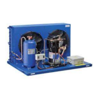
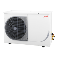
This instruction applies to fan-cooled
condensing units for the refrigerants stated
page 3-4.
2 – Versions
Version N0/A00
Version, for solder connection, has a nitrogen
holding charge. The units are designed for use
in refrigeration systems with capillary tube and
are to be treated as compressors concerning
evacuation and refrigerant charge.
Version N1
Version, which is supplied without refrigerant
receiver but with one stop valves and a nitrogen
holding charge, is designed for use in
refrigeration systems with capillary tube. The
units are to be treated as compressors
concerning evacuation and refrigerant charge.
Version N2
Version, which is supplied without refrigerant
receiver but with two stop valves and a nitrogen
holding charge, is designed for use in
refrigeration systems with capillary tube. The
units are to be treated as compressors
concerning evacuation and refrigerant charge.
Version T2/A01 without pressure control
Version without pressure control, which
is
supplied with refrigerant receiver, two stop
valves and a nitrogen holding charge, is
designed for use in refrigeration systems with
expansion valve.
The refrigerant receiver is approved for max.
32
bar operating pressure (see receiver label) and
is HP marked.
Units according to British Standard 1608
and approved by UL (UL identiable through
additional label) are supplied with a fusible
plug.
In the event of re, the fuse will melt before the
temperature reaches 150°C.
Version T2/A04 with pressure control
Version with pressure control is supplied with
refrigerant receiver, two stop valves and a
nitrogen holding charge.
The refrigerant receiver is approved for max.
32
bar operating pressure (see receiver label) and
is HP marked.
The units are delivered with a combined high
and low pressure control type KP17W, KP17WB
or with a high pressure control type KP7W.
The pressure controls KP17W/KP17WB and
KP7W are in compliance with the safety
standard EN 378-2.
The high pressure controls are set to cut out at
18 bar / R134a and 27 bar /R404A and R452A.
The low pressure control cuts out at 0 bar
(factory presetting). Indications in bar
overpressure (P
e
).
Version T0 without pressure control
Version without pressure control is supplied with
refrigerant receiver and a nitrogen holding
charge; it is designed for use
in refrigeration
systems with expansion valve
and is to be
completely soldered.
The refrigerant receiver is
approved for max.
32 bar operating pressure
(see receiver label) and is HP marked.
Units according to British Standard 1608
and
approved by UL (UL identiable through
additional label) are supplied with a fusible
plug.
In the event of re, the fuse will melt before the
temperature reaches 150°C.
Version T0 with pressure control
Version with pressure control is supplied with
refrigerant receiver and a nitrogen holding
charge.
It is designed for use in refrigeration
systems
with expansion valve and is to be
completely
soldered. These units are supplied
with a high pressure control type CC.
Version T1
Version without pressure control is supplied with
refrigerant receiver and a nitrogen holding
charge; it is designed for use
in refrigeration
systems with expansion valve
and is to be
completely soldered.
3 – Installation
Installation, maintenance and commissioning
must be carried out by qualied specialists only!
All connections, i.e. solderings and are joints,
are to be made professionally.
Protect the surroundings against admittance of
unauthorised persons. Pay attention to sucient
ventilation.
Remove transport safety devices, if any.
Mount the condensing unit horizontally. Use
the correct tube diameters.
Prevent any vibrations. Avoid smoking and
open re.
Refrigerant is to be removed and disposed of
professionally.
Assembly of the condensing units
Prepare the tube connections from the
evaporator.
It is recommended to use a drier with 3Å
molecular sieves, e.g. Danfoss type DML.
Use only dry components and avoid moisture
entering the system.
The system components must not contain any
chlorine, mineral oil, or other oily substances.
Maximum test pressure must not exceed 32 bar.
4 – Refrigerant charging
Refrigerant charging (N0, N1, N2, T0, T1, T2,
A00, A01 and A04)
Fig. 2. The process descriptions below are based
on the equipment shown.
1. Suction stop valve
2. Discharge stop valve
3. Connection to suction side
4. Shut-o valve to vacuum pump
5. Shut-o valve to charging cylinder
6. Connection to discharge side
7. Shut-o valve to discharge side
8. Shut-o valve to suction side
9. Connection to vacuum pump
10. Connection to charging cylinder
When a vacuum of 0.5 mbar or lower has been
reached, shut o the connection to the vacuum
pump by closing all manifold valves.
Repeat the evacuating process once or twice if
necessary and then close all manifold valves.
Close the service connector of the suction stop
valve (1) by turning the spindle „anticlockwise“
to the rear stop.
Refrigerant charging must take place from
equipment not contaminated with refrigerants
containing chlorine.
For units with stop valves the rule is that
refrigerant should always be charged in liquid
form through the discharge stop valve of the
unit in order to avoid liquid hammer when the
unit is started. If this rule cannot be observed
the compressor is not to be started until the
pressure and the temperature of the
refrigerating system have been equalized.
Open valves (5) and (7) of the valve manifold
while keeping the other valves closed.
When all liquid has been transferred to the
discharge side of the unit close the service
connector of the discharge valve (2) by turning
the spindle „anticlockwise“ to the rear stop.
Remove all hose connections.
Fit the union nuts with blind caps on pressure
gauge connectors (1) and (2).
Fit and tighten up caps on the valve spindles.
5 – Evacuation
Evacuation (N2, T2, A01 and A04)
Fig. 2. The process descriptions below are based
on the equipment shown.
1. Suction stop valve
2. Discharge stop valve
3. Connection to suction side
4. Shut-o valve to vacuum pump
5. Shut-o valve to charging cylinder
6. Connection to discharge side
7. Shut-o valve to discharge side
8. Shut-o valve to suction side
9. Connection to vacuum pump
10. Connection to charging cylinder
Connect the discharge line to the suction stop
valve (1) of the unit.
Connect the suction line, via the lter drier, to
the discharge stop valve (2).
Make the connection (3) between the manifold
and the service connector of the suction stop
valve (1).
Make the connection (6) between the manifold
and the service connector of the discharge stop
valve (2).
Make the connection (9) between the vacuum
pump and the manifold (4).
Make the connection (10) between the
charging cylinder and the manifold (5).
Remove the protective caps from the spindles
of both stop valves (1) and (2).
Open valves (4), (7) and (8). Open stop valves (1)
and (2) to mid position. Start the vacuum pump.
Vacuum pumps, which are normally used for
refrigerants containing chlorine, cannot be
used with R134a, R404A/R507 and R452A.
Only a vacuum pump with special Polyolester
oil may be used for systems with refrigerant
containing FCKW, HFCKW and HFKW.
(Contact the pump supplier.)
Evacuation (T0, A00)
Evacuation takes place through the compressor
then process connector after complete
connection in the refrigerating circuit.
Plan sucient time for the evacuation as it
takes place from the low pressure side only,
unless additional measures were taken to speed
up the evacuation.
Vacuum pumps normally used for refrigerants
containing chlorine must not be used with
R134aand R404A/R507. Only a vacuum pump
with special Polyolester oil may be used for
systems with refrigerant containing FCKW,
HFCKW and HFKW. (Contact the pump supplier.)
6 – Electrical connections
Prepare the electrical connections while
evacuation is taking place. Do not start the
compressor until the vacuum has been broken.
Remove the cover over the terminal board.
Connect the leads.
It is impossible to start the unit without a
thermostat (1H) being connected or a lead
between 1 or 2, respectively, and L has been
established (g. 4-7).
Fig. 4. Wiring diagram for the compressor
series: P, T, N, F, S.
Fig. 5. Wiring diagram for the compressor
series: SC with CSR (starting and operating
capacitor).
Fig. 6. Wiring diagram for the compressor
series: TL, FR and SC condensing units with
pressure control.
Fig. 7. Wiring diagram for the compressor
series: SC condensing units with combined high
and low pressure control and CSR (starting and
operating capacitor).
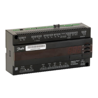
Fig. 8. Wiring diagram for the compressor
series: MP & ML condensing units.
1A. Main winding
1B. Start winding
1C. Start relay
1D. Winding protector
1E. Start capacitor
1F. Bleeder resistance
1G. Run capacitor
1H. Thermostat
1J. Fan
1K. Pressure control
Fit the terminal board cover.
Keep away ammables from the electrical
equipment.
7 – Declaration of conformity
• All our condensing units are complied with
low voltage directive 2014/35/EU and must
be incorporated during installation.
•
Low Voltage Directive 2014/35/EU
EN 60335-1:2012 + A11:2014- Household and
similar electrical appliances-Safety-Part 1:
General requirements-for all above mentioned
condensing units with compressor platforms
FR, GS, L, P, NF, NL, PL, SC and TL.
• Eco-design DIRECTIVE 2009/125/
EC,establishing a framework for the setting
 Loading...