24
Wiring
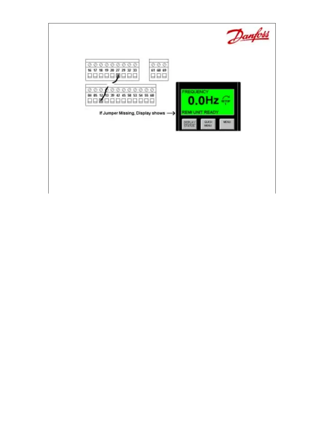
• Digital Inputs – 12 to 27 Enable
– Jumper terminal 12 (+24Vdc) to terminal 27 (enable command)
– Without jumper, bottom line of the display reads, “UNIT
READY” and it does not operate the motor. When this jumper
is made, the bottom line reads, “STANDBY”.
In its default state, the way it comes from the factory, a jumper or a connection is required for
operation. It must be connected between terminals 12 (24Vdc) and 27 (Digital Input), which
defaults to a “coasting stop inverse” command. If terminal 27 does not see 24Vdc, the drive
is not enabled and it does not operate. A display on the front of the drive gives a clear
indication when this occurs. After pressing the “Display/ Status” key, the bottom line reads,
“UNIT READY”. When ever this display is seen, a connection between terminals 12 and 27
is missing. Once this connection is made, the bottom line changes to read, “STANDBY”.
Digital Input Wiring covers the following:
Push-Button Switch
NO; NC; Multiple Offs, 3-wire S/S; Changing Reference
Continuous Switch (SPDT)
2-wire S/S; Start for Multiple Drives; SPDT Center-Off
Preset Speeds
Changing Setups
Encoders
 Loading...