Do you have a question about the Danieli Automation ID2202 and is the answer not in the manual?
Details the 6-pole connector, pin assignments, signals, and functions for power, outputs, and inputs.
Explains the fine-tuning of detection threshold via a rear panel potentiometer and its interaction with sensitivity settings.
Details electrical compatibility, pin differences, and wiring considerations when replacing older models.
Emphasizes that the photodetectors are intrinsically safe but require skilled personnel for use and maintenance.
Explains how to determine the optimal installation distance based on material temperature, diameter, and sensitivity settings.
Guides users through diagnosing and resolving common malfunctions.
The ID2202 is an infrared photodetector designed for industrial applications, primarily in steel hot rolling mill plants, but also suitable for continuous casting or detecting hot bodies in non-ferrous metals. It is an ON/OFF type device that detects the presence of hot materials by sensing infrared radiation (IR). This model, code D.A. 5122000031, replaces the older ID2000 and ID2200 models, offering additional functions and improved features.
The ID2202 utilizes an IR sensor to measure the quantity of infrared radiation within its field of view. A digital output activates when hot material is present, meaning the IR sensor's output signal exceeds a user-settable threshold. A second digital output, "HEALTHY," indicates the reliability of the detection, signaling anomalies in its functioning or when the detection threshold is approached, which could lead to errors. A digital input (SSEL) allows for selecting the HMD sensitivity, enabling reliable detection of both "cold" (T > 450°C) and "hot" (T > 650°C) materials. The device is designed for electrical supply by low-voltage continuous current, and its output connectors are protected against overloads and overvoltages.
The "MATP" digital output activates when an infrared source of sufficient intensity exceeds the detection threshold, which is determined by both the "coarse" sensitivity selection (via SSEL input) and the "fine" control (via potentiometer). The "HEALTHY" digital output is normally active and deactivates when anomalies occur, such as the IR signal being near the threshold, the TEST input being active without sufficient IR signal detection, internal overheating, or absence of power supply. These anomalies are also indicated by a two-color LED on the rear of the device. A "TEST" self-test function, when enabled, switches on an IR LED in front of the sensor, activating the MATP output to verify proper functioning.
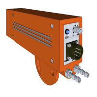
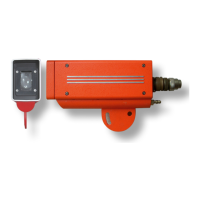
The ID2202's robust pressure-cast aluminum container includes a semi-circular support plate for fastening and orientation, and an integrated liquid cooling circuit. An optical window on the front allows the IR sensor to "observe" the material, with a green LED visible through it indicating material presence. The rear side features a 6-contact bayonet connector (MIL-C-5015), a two-color red/green LED for signaling, a sensitivity adjustment potentiometer, and 1/4" GAS threads for the cooling circuit.
The SSEL input allows for "coarse" sensitivity selection: OFF for HIGH sensitivity (like ID2200) and ON for LOW sensitivity (like ID2000). The potentiometer provides "fine" control. It is recommended to set sensitivity to HIGH if the material's temperature is near the lower measurable limit, but to avoid HIGH sensitivity if not necessary, as it increases the probability of detecting external sources like reflections or solar radiation.
The front green LED, along with the rear green LED and MATP output, activates upon material detection. This front LED aids in sighting: an operator can use a torch to identify the ID2202's field of view by observing when the LED switches on. The rear two-toned LED provides detailed status: green for material presence, rapid red flashes for signal near threshold (HEALTHY output deactivated), slow red flashes for internal overheating (HEALTHY output deactivated), and red flash in absence of a bar for strong background light.
Installation requires careful positioning to ensure the measurement field covers all material positions. A recommended installation distance is 60% of the maximum allowed distance for safety. Protection from extraneous light sources (light-bulbs, windows, reflections) is crucial, often requiring a protection screen. Cooling is recommended if ambient temperature exceeds 60°C, but excessive cooling should be avoided to prevent condensation. Protective screens are generally more effective against radiation-induced overheating than water cooling.
Periodic preventive maintenance is essential for the ID2202. This includes:
The ID2202 is supplied with the detector unit, a CD with Quick Reference, a connection cable, and a replacement glass. Spare parts include the complete detector, protection glass, and connection cable. Accessories like cooled protection and front protection with air cleaning are also available.
| Brand | Danieli Automation |
|---|---|
| Model | ID2202 |
| Category | Security Sensors |
| Language | English |