
M
morrisonmelissaSep 4, 2025
What does error code E3 mean on my Dantherm Fan?
- MMichael MillsSep 4, 2025
If the LED on your Dantherm Fan is flashing slowly with error code E3, this indicates a bypass damper issue.
What does error code E3 mean on my Dantherm Fan?
If the LED on your Dantherm Fan is flashing slowly with error code E3, this indicates a bypass damper issue.
How to fix a Dantherm Fan when the LED slowly flashes orange?
If the LED on your Dantherm Fan is slowly flashing orange, replace the air filters.
What does error code E9 mean on my Dantherm HCV 400 P1 Fan?
If the LED on your Dantherm Fan is flashing slowly with error code E9, this indicates a humidity sensor, RH% (Accessory) issue.
What does error code E8 mean on my Dantherm HCV 400 P1?
If the LED on your Dantherm Fan is flashing slowly with error code E8, this indicates an indoor air temperature sensor (T5) issue.
What does error code E7 mean on my Dantherm HCV 400 P1?
If the LED on your Dantherm Fan is flashing slowly with error code E7, this indicates an exhaust air temperature sensor (T4) issue.
What does error code E6 mean on my Dantherm Fan?
If the LED on your Dantherm Fan is flashing slowly with error code E6, this indicates an extracted air temperature sensor (T3) issue.
What does error code E5 mean on my Dantherm Fan?
If the LED on your Dantherm Fan is flashing slowly with error code E5, this indicates a supply air temperature sensor (T2) issue.
What does error code E4 mean on my Dantherm HCV 400 P1?
If the LED on your Dantherm Fan is flashing slowly with error code E4, this indicates an outside air temperature sensor (T1) issue.
What does error code E10 mean on my Dantherm HCV 400 P1 Fan?
If the LED on your Dantherm Fan is flashing slowly with error code E10, check outside temperature < -13 °C.
What to do if the LED flashes red on my Dantherm HCV 400 P1?
If the LED on your Dantherm Fan is flashing red, check the error code and rectify accordingly.
Details the unit's function, design, and airflow paths for residential ventilation.
Lists and describes the individual components of the HCV 400 unit.
Explains various optional accessories available for enhancing the unit's functionality.
Details the system's control architecture and how components interact.
Covers the process of installing the unit, including options and considerations.
Guides users on how to operate the unit and its various functions.
Provides information on maintenance, troubleshooting, and repairs.
Introduces the service manual and the HCV 400 residential ventilation unit.
Specifies the part number for the service manual.
Defines intended users and safety precautions for unit operation.
Emphasizes critical safety guidelines and liabilities for proper unit operation.
States that copying the manual without permission is forbidden.
Notes Dantherm's right to make changes without prior notice.
Lists directives and standards the unit complies with, including RoHS and EMC.
Provides guidelines for recycling the unit at the end of its lifetime.
Lists and defines abbreviations used throughout the manual.
Explains the meaning of the 'Warning' symbol and associated risks.
Explains the meaning of the 'Caution' symbol and associated risks.
Explains the meaning of the 'Notice' symbol for additional tips.
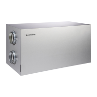
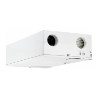
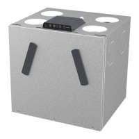
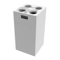
Explains the HCV range's purpose and design for energy-efficient home ventilation.
Shows a diagram of the unit with numbered components.
Describes the three variants of the HCV 400 unit and their differences.
Illustrates and explains the unit's function in different drain modes.
Illustrates the air flow paths through the unit in modes A and B.
Introduces the section describing the HCV 400 unit's standard components.
Details the construction and insulation of the unit's cabinet.
Explains the types of filters used and their purpose.
Describes the function of the reverse flow heat exchanger.
Explains the roles of the supply and extract fans.
Describes the bypass damper's function for summer cooling.
Explains the drain valves and condensate management.
Describes the humidity sensor and its role in demand mode.
Shows a diagram of the unit's control components and their layout.
Guides on installing optional accessories before or after unit commissioning.
Describes the optional silencer accessory.
Explains the function of the electric preheater for cold conditions.
Details the VOC sensor for air quality monitoring and demand mode.
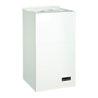
Describes the features and operation of the HRC 3 remote control.
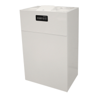
Explains the HCP 10 control panel as an alternative to the main control panel.
Mentions the HAC2 controller for connecting multiple accessories.
Lists replacement filter options.
Explains the placement and connection of the unit's main controls.
Shows the overall system control architecture diagram.
Illustrates the main PCB and control panel layout.
Details the external connections of the main PCB and wiring diagram references.
Explains the foil keypad, buttons, and LED indicators on the control panel.
Overviews the operation strategy in various conditions.
Explains the preheater function for cold conditions and supply air temperature.
Describes defrost mechanism and fireplace mode interaction.
Refers to user guide for bypass cooling and summer mode operation.
Guides on swapping duct connections between mode A and mode B.
Warns about disconnecting power before disassembling or operating switches.
Explains how to choose between mode A and mode B for duct connections.
Provides step-by-step instructions for switching the unit to mode B.
Instructs to swap the drain hose and plug as indicated for mode A/B.
Details how to swap the filter, especially the F7 pollen filter, for different modes.
Refers to page 22 for unit calibration procedures.
Warns that accessories must be swapped/installed according to the current operating mode.
Guides through unpacking, mounting, and installation processes.
Explains conditions under which warranty is forfeited or restricted.
Details steps for reporting damage and unpacking the unit.
Lists factors to consider when selecting an installation location.
Provides step-by-step instructions and measurements for mounting the unit to the wall.
Instructs on connecting the drain hose and siphon, with warnings about condensate.
Details how to connect ducts, ensuring correct diameter and insulation.
Advises on duct dimensions, noise, and vibration minimization using absorbers.
Warns about protecting ducts from dust and moisture before occupancy.
Explains how to connect the unit to a LAN for app access.
Mentions MODBUS connections for external modules and controllers.
Describes the unit's digital inputs and available options for settings.
Explains the importance of adjusting ventilation air for comfort and humidity levels.
Lists necessary tools for calibration, including PC tool and manometer.
Provides step-by-step instructions for calibrating fan speed using the control panel or PC tool.
Illustrates how to connect the manometer for calibration in Mode A and B.
Explains using USB connection and PC-Tool for parameter changes.
Advises checking unit functionality and power connection.
Lists necessary tools for updating firmware and setting parameters.
Provides step-by-step instructions for connecting a PC to the HCV 400 unit.
Details how to log in to the Dantherm PC-Tool.
Stresses adjusting air volumes according to legislation and calibration.
Shows a diagram of the unit's USB connections.
Introduces the section on using the remote controller for settings and status display.
Explains the three operation modes and minimum air change requirements.
Warns against turning off the unit to save energy due to condensation risk.
Describes manual operation mode and selecting ventilation speed.
Explains automatic ventilation adjustment based on weekly schedules.
Details demand-controlled operation using VOC/RH% sensors.
Explains how to use the control panel based on mounted accessories.
Shows an illustration of the control panel.
Details modes like Automatic bypass cooling and Manual bypass mode.
Warns about potential unit operation if bypass temperature settings are too low.
Explains modes like Summer cooling, Manual fan speed, Fireplace mode, Week program, Demand mode.
Describes filter/error display button and LAN interface functionality.
Explains Ethernet connection for BMS systems and IP address allocation.
Emphasizes preventative maintenance for efficiency and lifespan.
Provides a summary of minimum maintenance tasks and intervals.
Warns about performing inspections only by trained professionals and powering off the unit.
Details filter inspection and replacement procedures at 6-month intervals.
Describes annual filter replacement and alarm reset.
Guides on inspecting and cleaning internal components every two years.
Details visual inspection of external hoses, duct connections, and drain valves.
Explains how to understand and acknowledge possible operation errors.
Describes how the LED indicates filter status and operating errors.
Lists LED error codes and corresponding errors for software version 2.0 and above.
Explains how errors are displayed on the HRC3 remote control.
Mentions using PC-Tool to get detailed information from the error log.
Describes the process of resetting the unit and its subsequent error checks.
States that spare parts are available via Dantherm dealers.
Shows an exploded view of the unit with numbered spare parts.
Lists all available spare parts with order numbers for different unit variants.
Lists specifications like operating range, thermal efficiency, and cabinet dimensions.
Details performance metrics such as thermal efficiency and specific power input.
Provides cabinet dimensions, weight, and material properties.
Lists electrical specifications like voltage and power consumption.
Presents sound data for the HCV 400 P1 unit without a silencer.
Shows sound pressure levels at different distances for the HCV 400 P1.
Presents sound data for the HCV 400 P1 unit with a silencer.
Presents sound data for the HCV 400 P2 unit without a silencer.
Presents sound data for the HCV 400 P2 unit with a silencer.
Presents sound data for the HCV 400 E1 unit without a silencer.
Presents sound data for the HCV 400 E1 unit with a silencer.
Shows the overall wiring diagram of the unit.
Provides detailed dimensional drawings of the HCV 400 unit.
Shows dimensional drawings for the optional silencer.