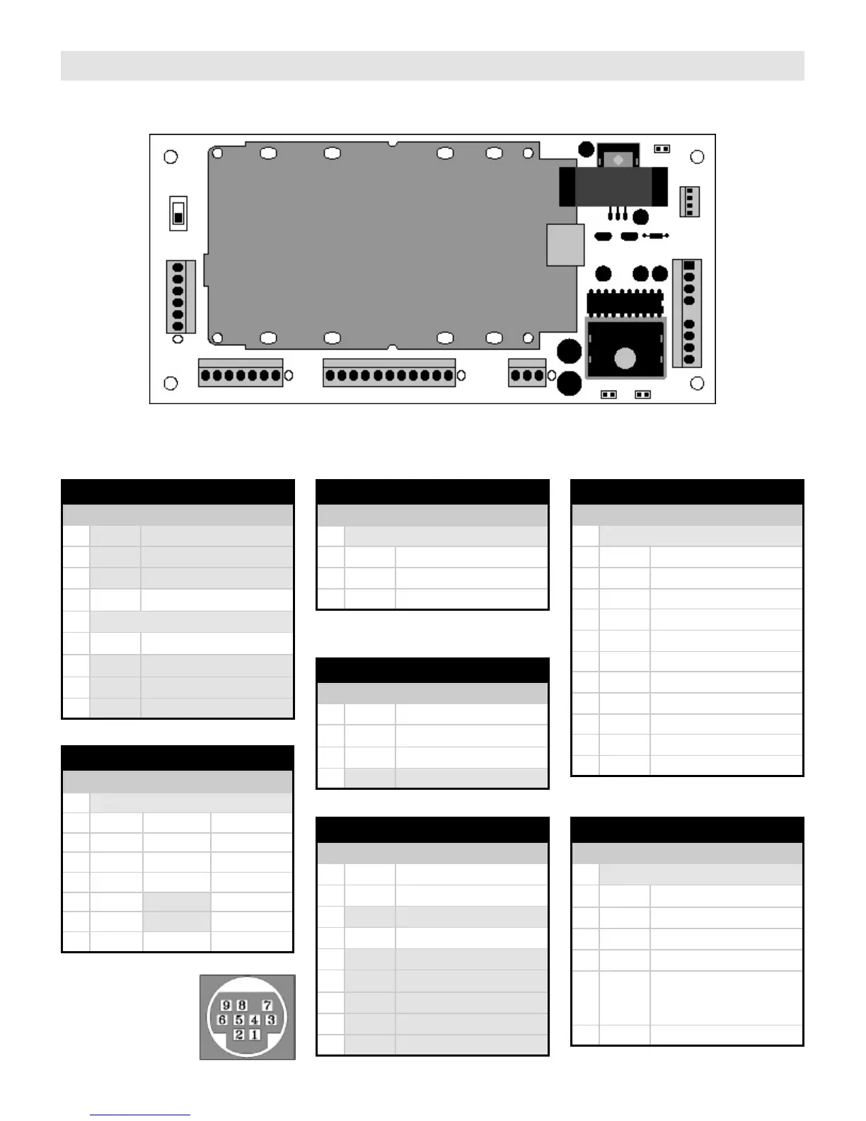
CONNECTOR DESCRIPTIONS
SERVICE
NORMAL
7 6 5 4 3 2 1
P5
Coin
Switches
P4
Keypad
8 7 6 5 4 3 2 1
P3
Display
12 11 10
9 8 7 6 5 4 3 2 1 4 3 2 1
P2
Speakers
9 8 7 6 5 4 3 2 1
P1
Power
P7
Remote
Service
Switch
4 3 2 1
J3
P1 – Power & External Speakers
Pin Name Description / Wire Color
1 Not used
2 Not used
3 Not used
4 +13VDC Power supply & Lamps WHT
5
6 Ground Power supply & Lamps BLK
7 Not used
8 Not used
9 Not used
Key
P3 – Display
Pin Name Ribbon Wire Color
1
2 SEGC BRN
3 SEGA RED
4 SEGG ORN
5 SEGB YEL
6 SEGE GRN
7 SEGF BLU
8 SEGD VIO
9 DIG4 GRY
10 DIG1 WHT
11 DIG2 BLK
12 DIG3 BRN
Peg
P2 – Speakers
Pin Name Wire Color
1 Peg
2 RSPK GRN
3 LSPK YEL
4 SCOM GRY
P4 – Keypad
Pin Name Mode P40
1
2 ROW3 GRN
3 ROW4 VIO
4 ROW1 BRN
5 ROW2 RED
6 COL3
7 COL2
8 COL1 BLU
Peg
Mode P41
7 8 9
* 0 #
1 2 3
4 5 6
3 6 9 #
2 5 8 0
1 4 7 *
P5 – Coin Switches
Pin Name Wire Color
1
2 #4 (50¢) WHT/BLU/BLK
3 #3 (25¢) BRN/RED/WHT
4 #1 (5¢) WHT/GRN/BLK
5 #2 (10¢) WHT/YEL/BLK
6 COINS WHT/GRN/BLK
WHT/YEL/BLK
BRN/RED/WHT
WHT/BLU/BRN
7 KBRDY WHT
Peg
Pin Name Description
1 RCH Right channel line level output
2 LCH Left channel line level output
3 5VDC +5VDC output
4 AGND Analog ground
5 PGND Power supply ground
9 SIN Serial data input
J3 – MP3 Player DIN Connector
6 +VIN Power supply input, +12V
7 SOUT Serial data output
8 IRIN IR signal input
P7 – Remote / Mute
Pin Name Shielded Wire Color
1 IRIN WHT
2 PGND SHIELD
3 5VDC RED
4 MUTE Mute signal out, active high
J3
MP3-DSP
"Line-Out"
 Loading...