Do you have a question about the Datakom DKG-105 and is the answer not in the manual?
Provides an overview of the control panel's design for user friendliness and non-volatile memory.
Details how to mount the unit in a standard panel opening using its spring mechanism.
Explains the necessary external fuses for mains and generator phases, and battery connection.
Describes the function and connection of each terminal for mains, generator, and control signals.
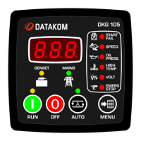
Explains the information shown on the digital display and indicator LEDs for status.
Details the various alarms, their triggers, and how they affect the unit's operation.
Describes the functions of OFF, AUTO, TEST, DISPLAY TEST, and PROGRAM modes.
| Panel Cut-out Size | 92 x 92 mm |
|---|---|
| Category | Genset Controller |
| DC Supply Range | 9-35 VDC |
| Alternator Voltage | Up to 300 VAC |
| Alternator Frequency | 45-65 Hz |
| Operating Temperature | -30°C to +70°C |
| Maximum Humidity | 95% RH (non-condensing) |
| Frequency | 45-65 Hz |
| Humidity | 95% RH (non-condensing) |