S3Z SERIES
INSTRUCTION MANUAL
CONTROLS
OUTPUT LED
The yellow LED indicates the output status.
STABILITY LED (S3Z…B01/C01/C11/F01)
The green LED ON indicates that the received signal has a safety
margin greater than 20% compared to the output switching value.
POWER ON LED (S3Z…G00)
The green LED indicates that the sensor is operating.
TRIMMER (S3Z…B01/C01/C11/F01/T51)
The trimmer can be used to adjust sensitivity; the operating distance
increases turning the trimmer clockwise.
ADJUSTMENT SCREW (S3Z…M01)
This control can be used to adjust the cutoff distance (6 turns screw);
the operating distance increases turning the control clockwise.
WARNING ONLY FOR TRIMMER (S3Z…B01/C01/C11/F01/T51)
MODEL: The trimmer rotation is limited to 250° by a mechanical stop.
Do not apply excessive torque when adjusting (max 0.05 Nm).
INSTALLATION
The sensor can be positioned by means of the two housing’s threaded
holes (M3) using two screws (M3x12 or longer or M2.5 passing screw,
0.5 Nm maximum tightening torque) with washers.
Various orientable fixing brackets to ease the sensor positioning are
available (please refer to the accessories listed in the catalogue).
CONNECTIONS
S3Z…B01/C01/C11/F01/M01/T51
+
BROWN
BLACK
1
4
10 … 30 Vdc
BLUE
3
0 V
OUTPUT
S3Z…G00
+
BROWN
1
10 … 30 Vdc
BLUE
3
0 V
M8 CONNECTOR
2
1
4
3
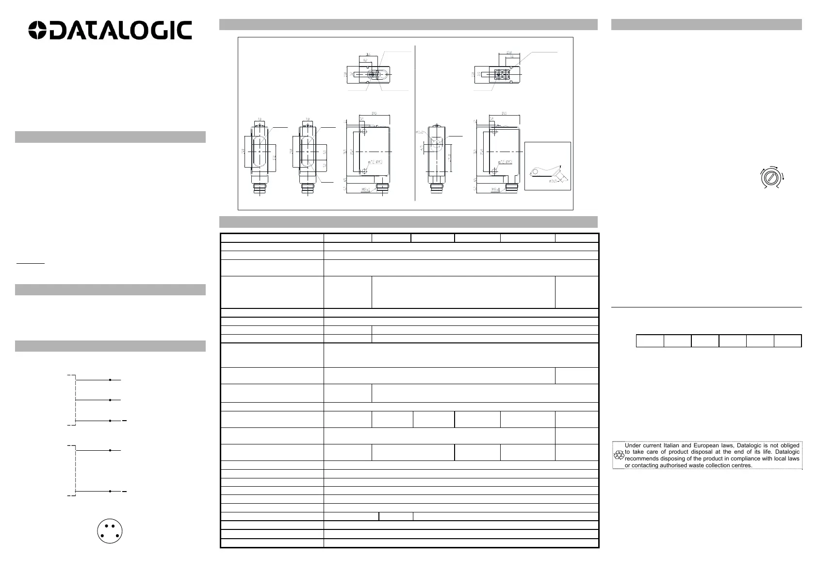
DIMENSIONS
S3Z
F01/G00
S3Z
B01/C01/C11/M01
Emitter and
Receiver
Coaxial
CABLE
VERSION
TRIMMER STABILITY LED
OUTPUT LED
POWER ON LED
(S3Z...G00)
Emitter or
Receiver
Receiver
Emitter
OUTPUT LED
S3Z...T51
TRIMMER
Dimensions in mm
TECHNICAL DATA
S3Z…T51 S3Z…B01
S3Z…C01 S3Z…C11 S3Z…F01/G00 S3Z…M01
Power supply: 12 … 24 Vdc (operating limit 10…30Vdc); reverse polarity protected
Ripple: p-p 10% max.
Current consumption
(output current excluded):
30 mA max.
Output: DARK; PNP
or NPN;
(short-circuit
protection)
LIGHT or DARK;
PNP or NPN;
(short-circuit protection)
LIGHT; PNP
or NPN;
(short-circuit
protection)
Output current: 100 mA max.
Output saturation voltage: 2 V max.
Response time: 500us max 1 ms max.
Switching frequency: 1KHz max. 500 Hz max.
Indicators: OUT LED (YELLOW)
STABILITY LED (GREEN) mod. B01/C01/C11/F01
POWER ON LED (GREEN) mod. G00
Setting:
TRIMMER (250°)
6 turns
screw
Operating temperature:
-25 … +50 °C
(UL)
-25 … +55 °C
Storage temperature: -40 … +70 °C
Operating distance (minimum): 2m on R2
reflector
see tab.1
50…150
mm
0…70 cm 0...20 m
50…250
mm.
Difference on White 90% / Gray
18%
---
22% @
200mm.
Emission type:
RED
(650 nm)
RED
(665 nm)
INFRARED
(850 nm)
INFRARED
(870 nm)
RED
(670 nm)
Ambient light rejection: according to EN 60947-5-2
Vibration: 0.5 mm amplitude, 10 … 55 Hz frequency, for every axis (EN60068-2-6)
Shock resistance: 11 ms (30 G) 6 shock for every axis (EN60068-2-27)
LIGHT/DARK selection: dependently from the model
PNP/NPN Output dependently from the model
Housing: Body PC and PBT / indicators cover PC
Lenses: PMMA PC PMMA
Protection class: IP67
Connections:
2 m cable 3.5 mm / M8-4 pole connector
Weight: 50 g. max. cable versions / 10 g. connector versions
SETTING
Alignment S3Z…B01/T51
Position the sensor and reflector on opposite sides.
Turn the sensitivity trimmer to maximum. Find the points where the
yellow LED (OUT) is switched ON and OFF in both vertical and
horizontal positions, and fix the sensor in the centre between these
points.
Optimum operation is obtained when the green LED is ON.
If necessary, reduce sensitivity using the trimmer, in order to detect very
small or transparent targets. In order to improve alignment, repeat the
procedure detailed above whilst progressively reducing the sensitivity.
Alignment S3Z…F01/G00
Position the sensors on opposite sides.
Find the points where the yellow LED (OUT) is switched ON and OFF in
both vertical and horizontal positions, and fix the sensor in the centre
between these points.
Optimum operation is obtained when the green LED is ON.
Alignment S3Z…C01/C11 (LIGHT mode)
Position the sensor and turn the sensitivity trimmer at minimum:
the green LED is ON and the yellow LED is OFF.
Place the target opposite the sensor.
Turn the sensitivity trimmer clockwise until the
yellow LED turns ON (Target detected state, pos.A).
Remove the target, the yellow LED turns OFF. Turn the trimmer
clockwise until the yellow LED turns ON (Background detected state,
pos.B). The trimmer reaches maximum if the background is not
detected. Turn the trimmer to the intermediate position C, between the
two positions A and B. The green LED must be ON.
For S3Z…C01/C11 models in DARK mode, the OUTPUT LED and the
output are inverted.
Alignment S3Z…M01
Position the sensor and turn the adjustment screw to maximum.
Place the target opposite the sensor at a slightly greater distance than
desired. Turn the screw counterclockwise until the sensor switches.
Verify the adjustment moving the target closer and further the sensor;
tune the adjustment if necessary.
It is recommended to operate with the stability LED turned ON.
TAB.1: S3Z…B01 max. operating distance table (meters)
AVAILABLE REFLECTORS
R1 R2 R3 R4 R5 R6
-B01
3 5 4.5 6 6 7
The sensors are NOT safety devices, and so MUST NOT be used in the
safety control of the machines where installed.
Datalogic S.r.l.
Via S. Vitalino 13 - 40012 Calderara di Reno - Italy
Tel: +39 051 3147011 - Fax: +39 051 3147205 - www.datalogic.com
Helpful links at www.datalogic.com: Contact Us, Terms and
Conditions, Support.
The warranty period for this product is 36 months. See General Terms
and Conditions of Sales for further details.
Under current Italian and European laws, Datalogic is not obliged
to take care of product disposal at the end of its life. Datalogic
recommends disposing of the product in compliance with local laws
or contacting authorised waste collection centres.
© 2005 - 2017 Datalogic S.p.A. and/or its affiliates ALL RIGHTS
RESERVED. Without limiting the rights under copyright, no part of this
documentation may be reproduced, stored in or introduced into a
retrieval system, or transmitted in any form or by any means, or for any
purpose, without the express written permission of Datalogic S.p.A.
and/or its affiliates. Datalogic and the Datalogic logo are registered
trademarks of Datalogic S.p.A. in many countries, including the U.S.A. and
the E.U. All other trademarks and brands are property of their respective
owners. Datalogic reserves the right to make modifications and
improvements without prior notification.
826002326 (Rev. G)
MIN
MAX
A
B
C
 Loading...