
B
barnesdavidAug 1, 2025
What causes a Generic Error in Datalogic Arex 400?
- JJohn DavisAug 1, 2025
The Generic Error counter for Datalogic Measuring Instruments is incremented each time the laser source detects an internal failure.
What causes a Generic Error in Datalogic Arex 400?
The Generic Error counter for Datalogic Measuring Instruments is incremented each time the laser source detects an internal failure.
What does Temperature Error mean for Datalogic Measuring Instruments?
The Temperature Error counter for Datalogic Measuring Instruments increases when the laser source temperature is outside of its operating range.
What does System Temperature error mean for Datalogic Measuring Instruments?
The System Temperature error counter for Datalogic Measuring Instruments increments each time the system temperature falls outside the operating temperature range.
What does Scan Head Temperature error mean for Datalogic Measuring Instruments?
The Scan Head Temperature error counter for Datalogic Measuring Instruments increments each time the scan head temperature falls outside the operating temperature range.
What does Service Interface error mean for Datalogic Measuring Instruments?
The Service Interface error counter for Datalogic Measuring Instruments increments each time the service interface detects a MMC error.
Why does my Datalogic Arex 400 display a Scan Head Temperature error?
The Scan Head Temperature error counter for Datalogic Measuring Instruments increases each time the scan head temperature falls outside of the operating temperature range.
What causes a System Temperature error on Datalogic Arex 400?
The System Temperature error counter for Datalogic Measuring Instruments increases each time the system temperature is outside of the operating temperature range.
General information for installers and manual scope regarding Class 4 Laser Product.
Details model number breakdown and characteristics of PRO and BASIC versions.
Procedures and warnings for unpacking the laser marker carefully.
List and images of all items included in the packaging.
Guidelines for securing and placing the laser marker safely.
Instructions for installing the control rack unit horizontally or vertically.
Instructions for mounting the scan head in various orientations.
Requirements for the marker's operating location and airflow.
Importance of ventilation and fume extraction during marking.
Detailed electrical, environmental, and physical specifications.
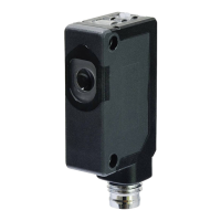
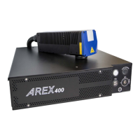
Overview of control rack and scan head components.
Specifications for marking field size and F-Theta scan lenses.
Pinout and details for various connectors like Safety Circuit, Command Box.
Descriptions of normal, error, and warning states with status LEDs.
Features and capabilities of the marking software.
Initial startup procedure, checks, and warnings.
Step-by-step guide for powering on using Key Selector or Command Box.
Customizing operating system language and keyboard layout.
Modifying network settings and IP address.
Steps for establishing a remote desktop connection.
Information on the Control Box accessory for marker control.
Details on the MARVIS™ solution for marking and validation.
Information on the fume extractor accessory for safety.
Procedures for routine upkeep of the laser marker.
Common problems, error states, and solutions.
How to obtain remote technical support via connection tool.
EC directives and CE marking requirements for machinery.
Process for hazard identification, risk estimation, and reduction.
Details on safety functions for different Arex™ models.
Nature, effects, and safety precautions for laser radiation.
Laser hazard classification from Class 1 to Class 4.
Risks associated with various viewing scenarios and reflections.
Hazards to human eyes and skin from laser exposure.
Creating and modifying graphics layouts in the software.
Testing and adjusting layouts before marking.
Specific operations for the MOPA fiber laser.
Configuring pulse profiles for different laser operations.
Step-by-step instructions for updating the software version.
Procedures for recovering the system using a USB disk.
Mechanical drawings and dimensions of the control rack.
Mechanical drawings and dimensions of the scan head.
| Brand | Datalogic |
|---|---|
| Model | Arex 400 |
| Category | Measuring Instruments |
| Language | English |