Connectors Specifications
User Manual 29
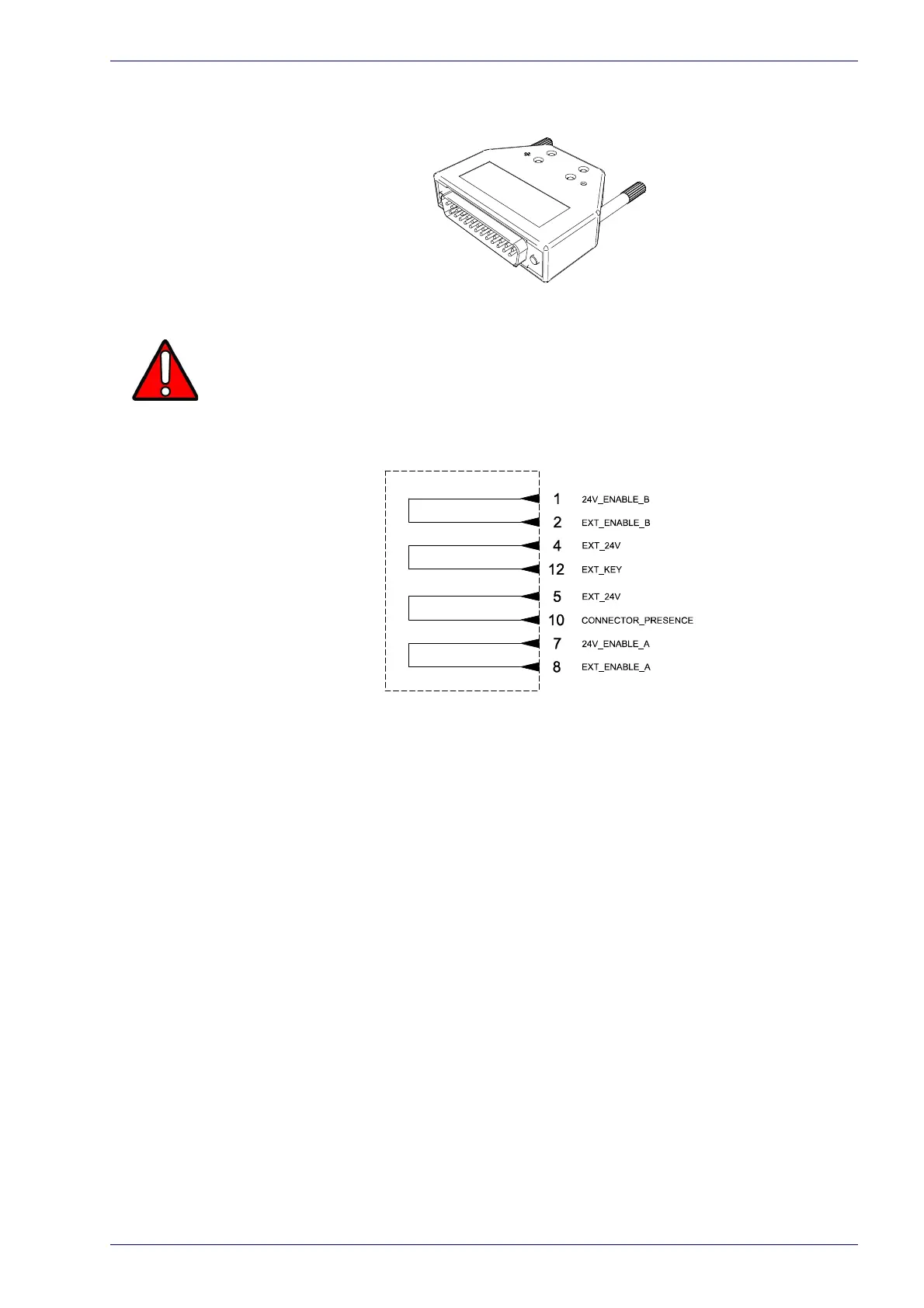
Muting Device
Sub-D, 25 pins, male, with shell.
Figure 9: Command Box Muting Device provided
W
ARNING
If the Command Box Muting Device provided is connected, the laser marker enable is
bypassed.
Internal electric diagram
Figure 10: Command Box Muting Device electric diagram
 Loading...