Technical Specifications
20
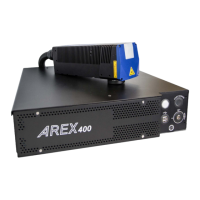
Arex™ 400
Product Description
Control rack
A description of the main parts of the control rack unit is provided here below::
Figure 1: Control rack overview (front and back panels view)
Front panel:
1. Status LED
2. Start Marking button
3. Key Selector
4. 2x USB 2.0 ports
Back panel:
5. Main Power Supply connection
6. Safety Circuit connector
7. VGA port
8. RS232 port
9. Encoder connector
10. Photocell connector
11. I/O connector (Axes Control)
12. Command Box connector (Laser Control)
13. Head Cable
14. Device Port 2
15. Device Port 1
16. LAN 1 port
17. LAN 3 port (
only for XXX-X6X models
)
18. LAN 2 port (
only for XXX-X6X models
)
19. 4x USB 2.0 ports
20. Earth ground connection
 Loading...