Troubleshooting
User Manual 77
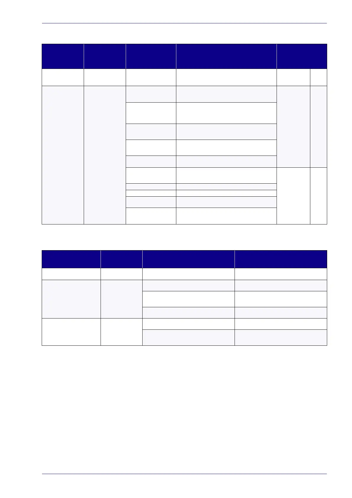
List of warning and error states
STATUS LED DESCRIPTION POSSIBLE CAUSE ACTION
OUTPUT STATE
COMMAND BOX
CONNECTOR
Blinking ORANGE
(1Hz)
Warning invalid start
se
quence
Incorrect turning-on
sequence
Set Key Switch to “0” and repeat the turning-on sequence.
See “Turning On sequence” on page 52
SYSTEM_ALARM
POWER_ON
ENABLE_OUT
OFF
OFF
OFF
Blinking RED
(1Hz)
System Error
Interlock error
- Check Safety Circuit connector signals (see “Safety Circuit”
on page 25)
- Check Safety Circuit connector presence
SYSTEM_ALARM
POWER_ON
ENABLE_OUT
ON
OFF
OFF
Connector Presence error
- Check if Command Box connector is present
- Check
CONNECTOR_PRESENCE
input signal of the Com-
mand Box connector (see “Command Box (Laser Control)” on
page 28
)
Rack Temperature error
Check the temperature of the environment where the control
rack is placed. The temperature must not exceed the opera-
tive limit
Scan Head
Temperature error
Check the temperature of the environment where the scan
head
is placed. The temperature must not exceed the opera-
tive limit
Scan Head
Connection error
Contact Datalogic Technical Support
Source Temperature error
Check the temperature of the environment where the control
rack
is placed. The temperature must not exceed the opera-
tive limit
SYSTEM_ALARM
POWER_ON
ENABLE_OUT
ON
OFF
OFF
Source generic error Contact Datalogic Technical Support
Source Power Supply error
Contact Datalogic Technical Support
Incorrect Firmware version
error
Contact Datalogic Technical Support
Back reflection error
Check the reflectance of the material to be marked. Marking
o
n high reflective material could damage the laser source.
Contact Datalogic Technical Support
List of problems related to laser marker states
PROBLEM
DESCRIPTION
STATUS LED POSSIBLE CAUSE ACTION
Laser marker never goes to WAIT
FOR START state
Blinking
GREEN
- Lighter™ Suite marking SW corrupted
- C:\ or D:\ drive corrupted
Restore the laser marker using USB recovery disk (see
“Recover the laser marker” on page 123
)
Laser marker never goes to READY
state
Steady
ORANGE
Key Switch selector in wrong position
Check the Key Switch is set to LASER ON (see “Turning
On sequence” on page 52)
EXT_ENABLE_A
and/or
EXT_ENABLE_B
contact are
LOW level or disconnected
Check
EXT_ENABLE_A
and
EXT_ENABLE_B
input sig-
nals on the Command Box connector are set to HIGH
lev
el (see “Command Box (Laser Control)” on page 28
)
LASER_STOP
signals is active
Check
LASER_STOP_A
and
LASER_STOP_B
input signals
on the Safety Circuit connector are both closed to GND
Laser marker never goes to
STANDBY SHUT
TER CLOSED state
Steady
GREEN
Key Switch selector in wrong position
Check the Key Switch is set to STANDBY (see “Turning
On sequence” on page 52
)
EXT_KEY
contact is LOW level or disconnected
Check
EXT_KEY
input signal on the Command Box con-
nector is set to HIGH level (see “Command Box (Laser
Control)” on page 28)
 Loading...