Bracket
(option)
Screws
M3x12
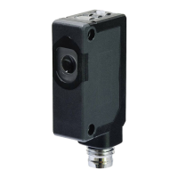
S3Z LASER SERIES
INSTRUCTION MANUAL
CONTROLS
OUTPUT LED
The yellow LED indicates the output status.
STABILITY LED (S3Z…B01/F01)
The green LED ON indicates that the received signal has a safety
margin greater than 20% compared to the output switching value.
POWER ON LED (S3Z…G00)
The green LED indicates that the sensor is operating.
TRIMMER (S3Z…B01/F01)
The trimmer can be used to adjust sensitivity; the operating
distance increases turning the trimmer clockwise.
ADJUSTMENT SCREW (S3Z…M01)
This control can be used to adjust the cutoff distance (6 turns
screw); the operating distance increases turning the control
clockwise.
LIGHT/DARK TRIMMER
This switch can be used to set light or dark operation mode.
WARNING (only for S3Z…B01/F01):
The trimmer rotation is limited to 250° by a mechanical stop.
Do not apply excessive torque when adjusting (max 0.05 Nm).
INSTALLATION
- Do not apply excessive impact on
the sensor during the installation
process, so as to prevent damage
or deterioration in the degree of
protection.
- To install the sensor, tighten the
mounting screws to a torque of
0.5 Nm or less.
- Install the Background
suppression type sensor head
perpendicular to the object
transfer as shown below to minimize sensing errors.
CONNECTIONS
The connections are compliant to the EN 60947-5-2 standard.
S3Z…B01/F01/M01
+
BROWN
BLACK
1
4
10…30 VDC
BLUE
3
0 V
OUTPUT
S3Z…G00
+
BROWN
1
10…30 VDC
BLUE
3
0 V
M8 CONNECTOR
2
1
4
3
TECHNICAL DATA
S3Z…B01 S3Z…F01/G00 S3Z…M01
Power supply: 12 … 24 VDC (operating limit 10…30VDC); (Class 2 UL508) reverse polarity protected
Ripple: p-p 10% max.
Current consumption
(output current excluded):
35mA max.
30mA max. mod.F01
15mA max. mod.G00
35mA max.
Output: LIGHT or DARK; PNP or NPN (short-circuit protection)
Output current: 100 mA max.
Output saturation voltage: 1.5 V max. 1.5 V max.
Response time: 250 us max.
Switching frequency: 2KHz max.
Indicators: OUTPUT LED (YELLOW); STABILITY LED (GREEN) mod. B01/F01
POWER ON LED (GREEN) mod. G00
Setting: Trimmer (250°) 6 turns screw
Detection Mode Setting: LIGHT/DARK Trimmer
Operating temperature: -10 … +55 °C (-10 … +50 °C UL Listed)
Storage temperature: -25 … +70 °C no freezing or condesation
Operating distance (minimum): 0.3...10 m on R2 0...30 m
20…250mm
(white paper 200x200 mm)
Insulating strength: 500 Vac 1 min., between electronics and housing
Insulating resistance:
>20 M 500 Vdc, between electronics and housing
Adjustable setting range: --- 40…300 mm
Difference on White 90% / Gray 18%: --- 10%
Minimum sensing object (typical):
Ø6 mm @ 3 m
(opaque)
Ø6 mm @ 3 m (opaque)
Ø0.2 mm @ 170 mm
(copper wire)
Emission type:
Red Laser diode(Emission wavelength: 650nm)
IEC/JIS CLASS1 * ; Maximum output: 7mW
Ambient light rejection: according to EN 60947-5-2
Vibration: 0.5 mm amplitude, 10 … 55 Hz frequency, for every axis (EN60068-2-6)
Shock resistance: 11 ms (30 G) 6 shock for every axis (EN60068-2-27)
Housing: Body PBT / indicators cover PC
Lenses: PMMA
Protection class: IP67
Connections:
2 m cable 3.5 mm / M8-4 pole connector **
Weight: 50 g. max. cable versions / 10 g. connector versions
* This product complies with FDA regulations 21CFR 1040.10 and 1040.11 based on Notice No.50.
** Use a UL Listed (CYJV/CYJV7) mating connector/cord assembly when using connector type as UL/c-UL listed products.
SETTING
Alignment S3Z…B01
Position the sensor and reflector on opposite sides.
Turn the sensitivity trimmer to maximum. Find the points where
the yellow LED (OUT) is switched ON and OFF in both vertical
Alignment S3Z…M01
Referring to the table below, adjust the distance of the photoelectric sensor
when necessary. The table explains the status of operation LED when the
operation mode is set to light ON.
and horizontal positions, and fix the sensor in the centre
between these points. Optimum operation is obtained when the
green LED is ON.
If necessary, reduce sensitivity using the trimmer, in order to
detect very small or transparent targets. In order to improve
alignment, repeat the procedure detailed above whilst
progressively reducing the sensitivity.
Alignment S3Z…F01/G00
Position the sensors on opposite sides.
Find the points where the yellow LED (OUT) is switched ON and
OFF in both vertical and horizontal positions, and fix the sensor
in the centre between these points.
Optimum operation is obtained when the green LED is ON.
Step
Distance
control
Adjusting procedure
1
Install a photoelectric sensor and the sensing
object. Turn the control counter-clockwise until the
operation LED turns OFF. Then turn clockwise until
the operation LED turns ON (point A).
2
Remove the sensing object, then the operation LED
turns OFF. Turn clockwise until the operation LED
turns ON, the background is detected (point B).
3
Set the middle point between point A and B as
point C.
DIMENSIONS
SAFETY PRECAUTIONS
CAUTION - use of controls or adjustments or performance of procedures
other than those specified in this mannual may result in hazardous radiation
exposure.
ATTENTION - L'utilisation des commandes, ainsi que les modifications de
réglages ou de procédures d’exécution autres que ceux specifiés dans ce
mode d'emploi peut entraîner une exposition à des rayonnements dangereux.
This product emits a visible laser beam. Do not stare into the beam directly.
Furthermore, do not look the laser which is reflected at a mirror-like object.
About safety standards of laser product, IEC60825-1 ”Safety of laser products”
has been stipulated by the IEC (International Electortechnical Commission).
This product is classified as “CLASS1 product” according to IEC60825-1
(2007). Use a UL Listed (CYJV/CYJV7) mating connector/cord assembly when
using connector type as UL/c-UL listed products.
CAUTION - This Product complies with
21 CFR 1040.10 and 1040.11 except for
deviations pursuant to Laser Notice No.
50, dated June 24, 2007, issued by
CDRH (Center of Devices and
Radiological Health) under FDA (Food
and Drug Administration).
ATTENTION - Ce produit est conforme
aux normes 21 CFR 1040.10 et 1040.11,
à l'exception des dérogations relatives au document « Laser Notice No.50 » du
24 juin 2007 émis par CDRH (Center of Devices and Radiological Health) de la
FDA (Food and Drug Administration).
Labels: Following “Warning label” and “Certification/ Identification label” are
affixed on this product according to IEC 60825-1 and laser regulation of FDA.
When this product will be incorporated into final device system which is
exported to the USA, make sure that Certification/Identification label is affixed.
The sensors are NOT safety devices, and so MUST NOT be used
in the safety control of the machines where installed.
Datalogic S.r.l.
Via S. Vitalino 13 - 40012 Calderara di Reno - Italy
Tel: +39 051 3147011 - Fax: +39 051 3147205 - www.datalogic.com
Helpful links at www.datalogic.com: Contact Us, Terms and Conditions,
Support.
The warranty period for this product is 36 months. See General Terms and
Conditions of Sales for further details.
Under current Italian and European laws, Datalogic is not obliged to take
care of product disposal at the end of its life. Datalogic recommends
disposing of the product in compliance with local laws or contacting
authorised waste collection centres.
© 2012 - 2017 Datalogic S.p.A. and/or its affiliates ALL RIGHTS RESERVED.
Without limiting the rights under copyright, no part of this documentation may
be reproduced, stored in or introduced into a retrieval system, or transmitted in
any form or by any means, or for any purpose, without the express written
permission of Datalogic S.p.A. and/or its affiliates. Datalogic and the Datalogic
logo are registered trademarks of Datalogic S.p.A. in many countries, including the
U.S.A. and the E.U. All other trademarks and brands are property of their
respective owners. Datalogic reserves the right to make modifications and
improvements without prior notification.
821003302 (Rev. C)
OK OK NO