Do you have a question about the Datalogic SG-BWS-T4 and is the answer not in the manual?
Explains the manual's scope and target audience for safe assembly and setup.
Identifies designers, manufacturers, and safety personnel as the primary audience.
Outlines the content covered, including installation, connection, commissioning, and maintenance.
Lists the items included in the SG-BWS-T4 safety system package.
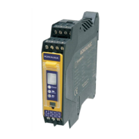
Details the physical components and user interface of the SG-BWS-T4 unit.
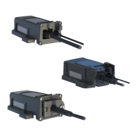
Describes the types of safety photocells compatible with the SG-BWS-T4 system.
Explains key functions like manual/automatic restarting and EDM monitoring.
Provides examples of where the SG-BWS-T4 system is used for protection.
Emphasizes critical safety points for correct and safe installation and operation.
Lists essential precautions for selecting and installing the safety system components.
Guides on optimal placement of safety photocells for effective protection.
Details the calculation and factors for determining the required safety distance.
Explains how to avoid issues caused by passive reflections from surfaces.
Addresses potential interference between safety devices and how to avoid it.
Provides instructions for mounting the SG-BWS-T4 control unit on an OMEGA/DIN rail.
Guides on how to physically install the safety sensors using their mounting features.
Offers crucial advice for safe and correct electrical wiring practices.
Explains how to connect external relays for machine control via the SG-BWS-T4.
Details the essential wiring for basic system testing and operation.
Provides a comprehensive overview of all terminal connections for the SG-BWS-T4 unit.
Outlines the wiring procedure for up to four safety photocells.
Details wiring for the SG-BWS-T4-2 model supporting up to eight photocells.
Describes how to connect external relays and enable the EDM function for monitoring.
Explains different reset modes and wiring for the push-button.
Describes the initial display sequences and what they signify for device readiness.
Details the procedure for aligning safety sensors and photocells for optimal performance.
Explains the LED and display indicators during normal system operation.
Details error codes and indicators for diagnosing system failures.
Lists recommended maintenance operations for ensuring system integrity and safety.
Outlines the terms, conditions, and duration of the product warranty.
Provides guidance on the environmentally compliant disposal of the product.
Presents detailed physical dimensions for the SG-BWS-T4 control unit.
Refers to other manuals for dimensions of compatible safety sensors.
An index listing all figures presented in the document.
An index listing all tables presented in the document.
| Model | SG-BWS-T4 |
|---|---|
| Manufacturer | Datalogic |
| Input Voltage | 24 V DC |
| Protection Rating | IP65 |
| Compatibility | Datalogic devices |