SECTION 2
FEATURES AND OPERATION
2-1
001-4008-101/102
2.1 OVERVIEW
This chapter describes the connections, indicators, and operating characteristics of the Integra-TR. This
chapter is intended for system application and installation personnel.
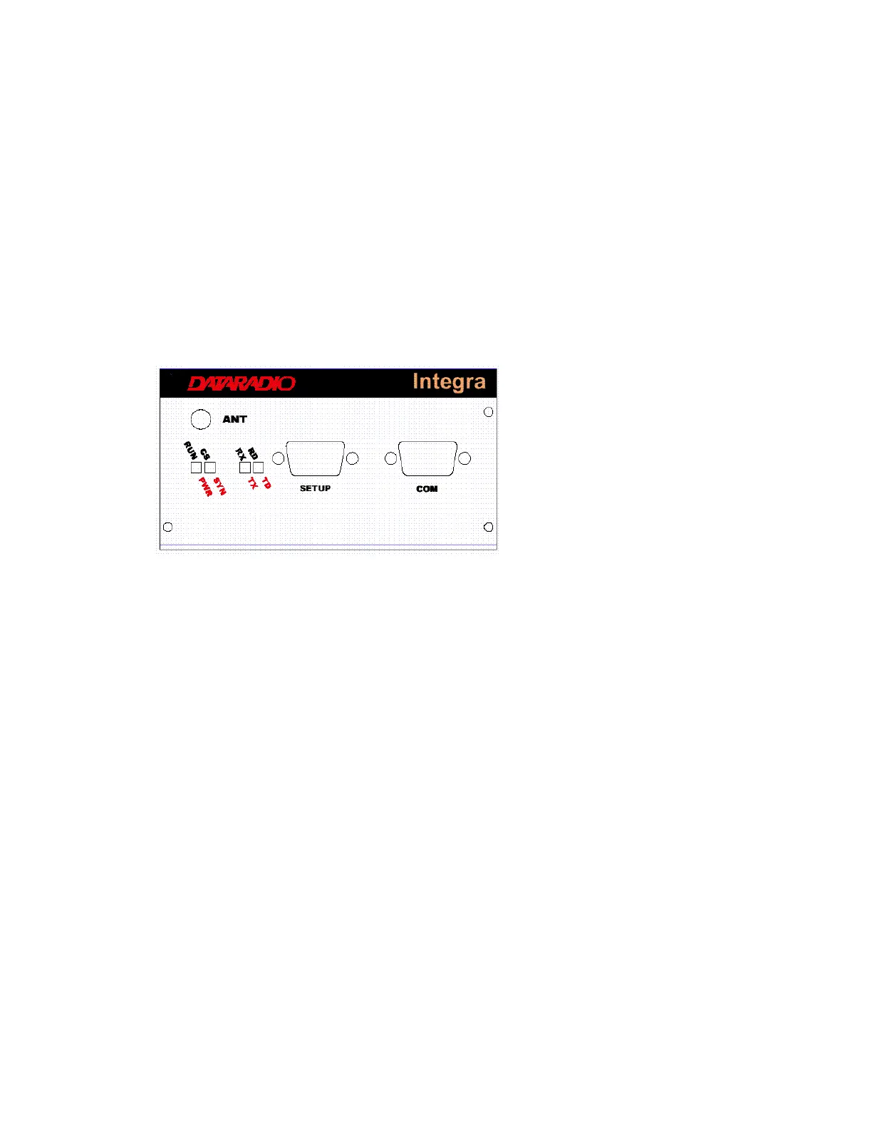
2.2 FRONT PANEL
The various front panel elements are described in the following sections.
Figure 2-1 Integra-TR Front Panel
2.2.1 Antenna Connector
Antenna connector is a female 50-ohm SMA- type. Units operated with a “rubber duck” antenna connected
directly to the antenna connector may exhibit unusual operating characteristics and high levels of reverse
power.
2.2.2 Connection to DTE
Integra-TR is configured as DCE. Most DTE should be connected using a nine-conductor pin-to-pin
“straight” cable. Some RTUs or PLCs may require a special cable to route the signals correctly. See the
documentation for your data equipment for further information.