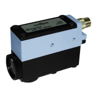
INSTALLATION / MONTAGE
• The TL80 has tapped holes (M5x5.5) provided on three sides, allowing six different assembly positions. The mounting position
does not affect the functioning of the device. Assembly on "silent block" is advisable when the machine causes strong vibrations.
• The reading direction may be reversed by simply swapping the cap with the lens: the reading may be from the front of from the
side.
• The distance of the optic head from the reading surface must be equal to the focusing distance of the lens. The optic head is
usually assembled at 90° to the reading surface.
• If the material is very shiny (i.e. plastic or metal plate) it is advised to tilt the reading head 5° to 20° in relation to the material that
has to be read and to the direction of its movement (see fig.2).
• Select the emission light type by means of the proper switch (fig.5): red or infrared for models TL80F-05X, green or red for all other
models, according to table 2.
• To install the optic fibre, insert the fibre connector on the TL80 body, in the correct position indicated by fig.6.
• Der TL80 bietet dank seiner auf drei Seiten angeordneten Befestigungsbohrungen sechs verschiedene Installationsmöglichkeiten.
Die Funktionalität des Geräts wird dadurch nicht beeinflusst. Sollte die Maschine starke Vibrationen verursachen, empfehlen wir
das Gerät gummigelagert anzubauen.
• Der Lichtaustritt kann durch gegenseitiges tauschen von Linse und Abdeckkappe geändert werden, sodass die Erfassung der
Marke sowohl von vorn als auch von der Seite erfolgen kann.
• Der Abstand des Druckmarkenlesers zur Leseoberfläche muss der Fokusdistanz der Linse entsprechen und ist gewöhnlich im 90°
Winkel zur Leseoberfläche anzubauen.
• Ist das abzufragende Material glänzend (z.B.. Kunststoff oder Metall), empfehlen wir den Druckmarkenleser ca. 5° bis 20° zum Material
und zur Bewegungsrichtung zu neigen (s.fig.2).
• Wählen Sie das entsprechende Senderlicht mittels Schiebeschalter (s.fig.5): rot oder infrarot für die Modelle TL80F-05X, grün oder
rot für alle anderen Modelle gemäss Tabelle 2.
• Um die Fiberoptik zu adaptieren, schrauben Sie den Lichtleiter gemäss Zeichnung (s.fig.6) in der entsprechenden Position am
Gehäuse des TL80 fest.
NPN/PNP OUTPUT SELECTION / NPN/PNP UMSCHALTUNG
On the TL80 unit it is possible to select NPN or PNP output (white wire). To select the output remove the four screws of the cover
near the cable and change the jumper position (see fig.3). Verify the gasket position when replacing the cover.
Der TL80 ermöglicht die Auswahl zwischen NPN oder PNP Ausgang (weisses Litze). Hierzu lösen Sie die 4 Deckelschrauben und
nehmen den Deckel ab. Ändern Sie die Position des Jumpers (s.fig.3). Überprüfen Sie vor dem Zusammenbau den richtigen Sitz der
Deckeldichtung. Verfahren Sie dabei in umgekehrter Reihenfolge.
DELAY SELECTION / IMPULSVERLÄNGERUNG
On the TL80 unit it is possible to enable a delay function of the output switching. To enable or disable this function, remove the four
screws of the cover near the cable and change the jumper position (see fig.3). Verify the gasket position when replacing the cover.
The standard TL80 unit is supplied with delay function disabled.
An dem TL80 kann eine Impulsverlängerung aktiviert werden. Um diese Funktion zu de- oder aktivieren, lösen Sie die 4
Deckelschrauben und nehmen den Deckel ab. Ändern Sie die Position des Jumpers (siehe fig.3). Überprüfen Sie vor dem
Zusammenbau den richtigen Sitz der Deckeldichtung. Verfahren Sie dabei in umgekehrter Reihenfolge.
Die werkseitige Einstellung bei Auslieferung ist mit deaktivierter Impulsverlängerung.
MAINTENANCE / WARTUNG
The TL80 unit is enclosed in a metal housing and requires little maintenance. Stains on the lens affect the detecting characteristics
substantially. Wipe any stain from the lens using a soft cloth.
Do not use solvents or other substances when cleaning the lens.
Der TL80 ist in einem Metallgehäuse ausgeführt und beansprucht nur wenig Wartungsaufwand. Schmutz auf der Linse beeinflusst
die Erfassung enorm. Reinigen Sie daher sorgfältig die Linsen. Benutzen Sie hierzu ein weiches Tuch. Zur Reinigung der Linse
benutzen Sie keine Lösungen oder andere aggresiven Substanzen.
ANALOG OUTPUT (not for M12 connector models) / ANALOGAUSGANG (ausgenommen M12-Stecker Modelle)
The TL80 unit is provided with an analog output (grey wire). The analog output gives a voltage proportional to the reflected light.
Analog output allows to evaluate the contrast resolution between mark and background, to choose the correct emission.
Der TL80 ist mit einem Analogausgang ausgestattet (graues Kabel). Die Spannung des Analogausganges ist proportional zum
reflektieten Lichts. Dieser Analogausgang ermöglicht Ihnen den Kontast zwischen Marke und Hintergrund zu beurteilen um so die
richtig Senderfarbe auswählen.
OVERALL DIMENSIONS/ABMESSUNGEN
18
34.3
Ø29
71
Ø25
7
44.5
Ø25
Ø33
21
Ø5
58.5
2841.5
87
30
4
75
24
28
36.5
15.5
N°.8 M5x5
28 LENS
18 LENS
AMPHENOL CONNECTORM12 CONNECTOR
62.5
Figure 1
αα
α
must range from 5° to 20°
α
muß im Bereich 5° bis 20° liegen
Figure 2
NPNPNP
No delay Delay
Figure 3
ENGLISH DEUTSCH *TL80 9mm *TL80 18mm *TL80 28mm TL80F G/R TL80F IR/R
Supply voltage Betriebsspannung
10 … 30 Vdc (max. ripple 2 Vpp) with protection against polarity inversion / mit Verpolschutz
Consumption Stromaufnahme
80 mA max.
Emission
Selectable by an
internal switch
Sender
umschaltbar durch internen
Schiebeschalter
Visible green LED (526 nm) or red LED (630 nm)
LED grün (526 nm) oder rot (630 nm)
Infrared emitter (880 nm)
Infrarot Sender (880 nm)
Visible red LED (635 nm)
LED rot (635 nm)
Output
Selectable by an
internal jumper
Ausgang
umschaltbar durch internen
Jumper
NPN or PNP; Pull up/down resistance / Pull up/down Widerstand = 10 kΩ
Output current Ausgangsstrom
200 mA max. with short circuit protection / mit Kurzschlussschutz
Saturation voltage Sättigungsspannung
1.2 V (NPN), 2.2 V (PNP) at maximum output current / bei max. Ausgangsstrom
Timing delay
Enabled by an
internal jumper
Impulsverlängerung
aktivierbar durch einen
internen Jumper
20 ms OFF delay / Abfallverzögerung
Operating distance Tastweite
9 mm ± 2 18 mm ± 2 28 mm ± 3
See optic fibre reading diagrams
Siehe Fiberoptik Lesediagramme
Spot dimension Lichtfleckgrösse
1.5x5 mm² at 9 mm 2x7 mm² at 18 mm 3x10 mm² at 28 mm
Response time Ansprechzeit
50 µs 50 µs 166 µs 50 µs 50 µs
Switching frequency
(dark/light ratio = 1:1)
Schaltfrequenz
(hell/dunkel Relation = 1:1)
10 kHz 3 kHz 10 kHz
Switching threshold Schaltschwelle
Adjustable by an external knob / Einstellbar durch einen externen Knopf
Dark/light function Hell-/Dunkel-Schaltung
Selectable by an external switch / Wählbar über einen externen Schalter
Analog output Analogausgang
0 ... 5 Vdc; Output resistance / Ausgangswiderstand = 10 kΩ
Ripple Restwelligkeit
35 mVpp
max
Housing material Gehäusematerial
ZAMA
Protection class Schutzart
IP67
Operating
temperature
Betriebstemperatur
-10 … +55 °C
Storage temperature Lagertemperatur
-20 … + 70 °C
Connections Anschlüsse
3 m ∅ 5 mm cable; 3 m ∅ 5 mm cable with Amphenol connector; M12 connector
Kabellänge 3 m ∅ 5 mm; Kabellänge 3 m ∅ 5 mm mit Amphenolstecker; M12-Stecker
Weight Gewicht
550 g.
Tabelle 1
(*) The lenses with focusing distance of 9 mm and 18 mm are interchangeable on the same body (TL80-01XX and TL80-06XX), while the 28 mm lens can only be
mounted on the TL80-02XX body.
Die Linsen mit einem Fokusabstand von 9 mm und 18 mm sind am selben Gerät austauschbar (TL80-01XX und TL80-06XX), während die 28 mm Linsen nur am
TL80-02XX angebracht werden kann.
SERIES TL80
INSTRUCTION MANUAL
BEDIENUNGSANLEITUNG