1
2
34
5
6
7
2
3
1
4
CABLE CONNECTION - CONNECTOR PINOUTS
The TL80 is provided with a 3 m connecting cable (except for M12 versions).
Connect the wires as shown in fig.4.
• If the TL80 housing is connected to ground and the power supply is isolated from ground or
vice versa; connect the shield to 0V.
• If both TL80 and power supply are connected to ground; leave the shield unconnected.
Note: Avoid placing the TL80 and its connecting cable close to electric motors, high voltage
lines and other electromagnetic noises.
In the following figure the connectors are viewed from the external side of the housing.
KABELANSCHLUSS - ANSCHLUSSBELEGUNG
Der TL80 ist mit einem 3 m Anschlusskabel ausgestattet ( ausser M12-Stecker-Versionen).
Schliessen Sie die Kabel wie in Figur 4 gezeigt an.
• Ist das TL80 Gehäuse geerdet und das Netzteil für die Spannungsversorgung isoliert montiert (oder
umgekehrt), dann ist der Schirm an 0 V anzuschliessen.
• Sind beide TL80 und Netzteil geerdet, dann schliessen Sie den Schirm nicht an.
Hinweis: Vermeiden Sie es den TL80 und seine Anschlusskabel in der Nähe von elektrischen Motoren,
Hochspannungsleitungen und anderen elektromagnetischen Störfeldern zu plazieren.
In der folgenden Zeichnungen sind die Anschlüsse der Gehäuseansicht aufgezeigt.
CABLE / KABEL AMPHENOL CONNECTOR / AMPHENOL STECKER M12 CONNECTOR / M12 STECKER
white / weiss NPN/PNP output / Ausgang NPN/PNP
grey / grau
Analog output / Analogausgang
brown / braun
10...30 Vdc
blue / blau
0 V
Shield / Schirm
1 NPN/PNP output / Ausgang NPN/PNP
2 10...30 Vdc
4 Analog output / Analogausgang
60 V
7 Shield / Schirm
1
2
3
4
10...30 Vdc
Shield / Schirm
NPN/PNP output / Ausgang
0 V
Figure 4
GREEN/RED OR RED/INFRARED EMISSION SELECTION
The TL80 unit gives the possibility of choosing red or green emission (red or infrared for optic fibre
model -05X), to get the best resolution of the contrast between mark and background. To select the
emission color, position the switch shown in fig.5, according to table 2. The standard TL80 unit is
supplied with the emission selected to green (for green/red emission models) or infrared (for
red/infrared emission models).
SENDERAUSWAHL GRÜN/ROT ODER INFRAROT
Der TL80 ermöglicht eine Auswahl zwischen rotem oder grünem Sendelicht (rot oder infrarot bei Lichtleiter-
modellen -05X); und erreicht so die bestmögliche Kontrastauflösung zwischen Marke und Hintergrund. Um die
entsprechende Senderfarbe gemäss Tabelle 2 anzu wählen, positionieren sie den Schalter wie in Figur 5
gezeigt. Werkseitige Einstellung des TL80 ist Senderfarbe grün (für grün/rot Sendermodelle) oder
infrarot (für rot/infrarot Sendermodelle).
R
G/IR
LD
OUTPUT
G/IR
R
Figure 5
Sender Rot
Sender
Grün oder Infrarot
red emission
emission
green or infrared
Figure 6
Table 2
THRESHOLD ADJUSTMENT AND LIGHT/DARK SELECTION
Words used in the description below have the following meaning:
BACKGROUND: The surface that the TL80 must not detect
MARK: The symbol on the surface that must be
detected by the TL80
CONTRAST RATIO: Ratio of mark to background
LIGHT MARK: Mark lighter than background
DARK MARK: Mark darker than background
To detect dark marks on light backgrounds:
1. Turn the light/dark selector switch (indicated in fig.7) to the
dark mark detection side (D).
2. Place the light spot of the TL80 unit over the dark mark.
3. Turn the threshold adjustment knob until the output LED is
ON (circular red LED fig.7). The triangular red LEDs indicate
the direction of rotation.
4. Place the light spot over the background and repeat point 3
with opposite rotation to switch ON the output LED.
5. Turn the adjustment knob again as in point 3 with the original
rotation for 1/2 the number of turns counted in point 4.
To detect light marks on dark backgrounds: follow the same set
up procedures, but turning the light/dark selector switch to the
light mark detection side (L).
To detect marks with slight color contrasts, it is necessary to
power up the TL80 for some minutes before adjusting the
threshold. When marks are on a transparent background, tilt the
TL80 unit as shown in figure 2 and set the light/dark selector
switch properly.
threshold
adjustment
knob
emission
switch cover
clockwise
indicator
counterclockwise
indicator
dark-light
switch
output LED
LD
OUTPUT
G/IR
R
umschaltung
Sendelicht-
anzeige
Drehrichtungs-
Hell/Dunkel
Umschaltung
Ausgans-LED
Drehrichtungs-
anzeige
Empfindlich-
keitseinstell-
knopf
Figure 7
EINSTELLUNG DER SCHALTSCHWELLEN UND HELL/DUNKEL UMSCHALTUNG
Verwendete Begriffe und ihre Bedeutungen:
H
INTERGRUND: Ist die Oberfläche die nicht vom TL80 erfasst wird.
DRUCKMARKE: Ist die Marke oder das Symbol auf dem Hintergrund das der TL80
erfassen muss.
KONTRAST Verhältnis zwischen Druckmarke zu Hintergrund.
H
ELLE MARKE: Die Marke die heller als der Hintergrund ist.
D
UNKLE MARKE: Die Marke die dunkler als der Hintergrund ist.
Erfassung einer dunklen Marken auf hellem Hintergrund:
1. Stellen Sie den Hell/Dunkel-Schalter auf dunkle Marke (Schalterstellung D wie in
Figur 7 gezeigt) .
2. Plazieren Sie die Marke unter dem Lichtfleck des TL80.
3. Drehen Sie den Einstellknopf bis die Ausgangs LED an geht (runde rote LED Fig.
7). Die roten Drehrichtungs-LED’s zeigen dabei die Drehrichtung an.
4. Plazieren Sie nun den Hintergrund unter dem Lichtfleck und wiederholen Sie
Punkt 3 mit der inversen Drehrichtung, bis die Ausgangs LED leuchtet. Zählen
Sie dabei die Umdrehungen.
5. Drehen Sie den Einstellknopf, wie in Punkt 3 beschrieben, wieder um der Hälfte
der gezählten Umdrehungen zurück.
Um helle Marken auf dunklem Hintergrund erfassen zu können, folgen Sie den selben
Anweisungen, doch stellen Sie den Hell/Dunkel-Schalter auf helle Marke
(Schalterstellung L s.Figur 7). Um Marken mit geringem Kontrast erfassen zu können
ist es notwendig den TL80 erst für einige Minuten zu betreiben, bevor die
Schaltschwelle eingestellt wird. Ist die Marke auf einem transparenten Hintergrung
neigen Sie den TL80 wie in Figur 2 dargestellt, stellen den Hell/Dunkel Schalter
entsprechend ein und verfahren nach o.g. Einstellanleitung.
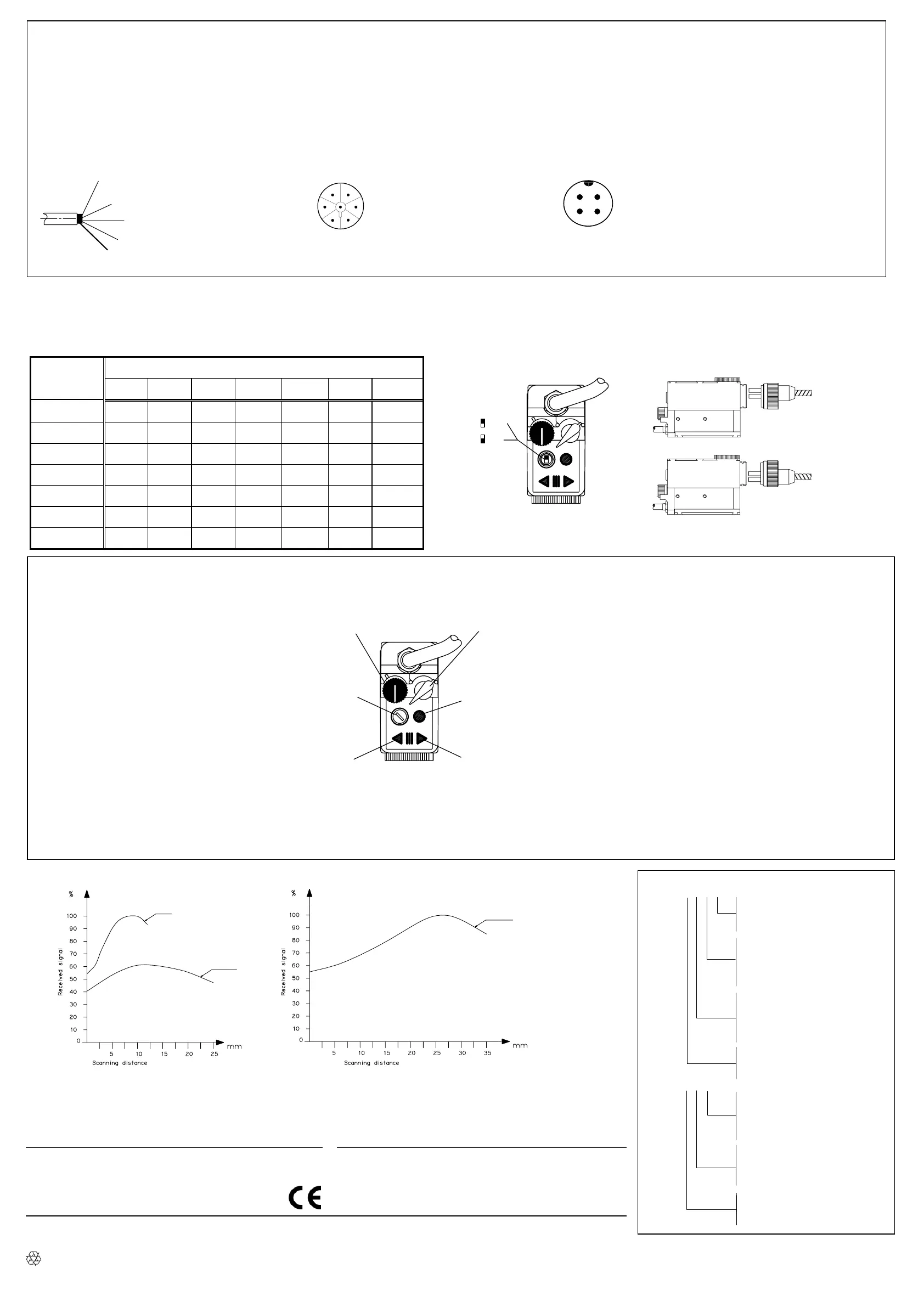
READING DIAGRAMS - LENS MODELS / LESEDIAGRAMME - MODELLE MIT LINSEN MODELS / MODELLE
9 mm Objektiv
18 mm Objektiv
18 mm Lens
9 mm Lens
/
Tastweite
28 mm Lens
28 mm Objektiv
/ Tastweite
Figure 8
FIBRE MODELS / LICHTLEITERMODELLE
Optic fibres for TL80 are available with several models that differ for spot type and mechanical characteristics in order to fit a wide range of
application requirements. Reading diagrams for fibre optic models are given in the fibre optic documentation.
Für den TL80 stehen eine Vielzahl unterschiedlicher Lichtleiter zur Verfügung, die sich hinsichtlich des Lichtfleckes und der mechanischen
Charakteristik unterscheiden.Die entsprechenden Lesediagramme dieser Lichtleiter sind in der Lichtleiterdokumentation enthalten..
TL80 - X X X X
none = rectangular and vertical spot
L = rectangular and horizontal spot
leer = rechteckiger und vertikaler Lichtfleck
rechteckiger und horizontaler Lichtfleck
1 = cable
2 = cable plus Amphenol connector
5 = M12 connector
Kabel
Kabel mit Amphenol-Stecker
M12-Stecker
1 = focusing distance of 9 mm
2 = focusing distance of 28 mm
6 = focusing distance of 18 mm
Tastweite 9 mm
Tastweite 28 mm
Tastweite 18 mm
1 = PNP output
0 = NPN output
NPN-Ausgang
PNP-Ausgang
TL80F - X X X
1 = cable
2 = cable plus Amphenol connector
5 = M12 connector
Kabel
Kabel mit Amphenol-Stecker
M12-Stecker
4 = green/red emission
5 = infrared/red emission
Sender Rot/Grün
Sender Rot/Infrarot
0 = NPN output
1 = PNP output
NPN-Ausgang
PNP-Ausgang
BACKGROUND
COLOR
MARK COLOR
MARKENFARBE
HINTERGRUND-
FARBE
WHITE
WEISS
BLUE
BLAU
GREEN
GRÜN
YELLOW
GELB
ORANGE
ORANGE
RED
ROT
BLACK
SCHWARZ
WHITE
WEISS
G / R R G / R G G G / R
BLUE
BLAU
G / R G / R G / R G / R R G / R
GREEN
GRÜN
R G / R G / R G / R R G
YELLOW
GELB
G / R G / R G / R G / R R G
ORANGE
ORANGE
G G / R G / R G / R G R
RED
ROT
G R R R G R
BLACK
SCHWARZ
G / R G / R G G R R
DECLARATION OF CONFORMITY
We DATASENSOR S.p.A. declare under our sole responsibility that these
products are conform to the 2004/108 CEE, 73/23 CEE Directives and
successive amendments.
WARRANTY
DATASENSOR S.p.A. warrants its products to be free from defects.
DATASENSOR S.p.A. will repair or replace, free of charge, any product
found to be defective during the warranty period of 36 months from the
manufacturing date. This warranty does not cover damage or liability
deriving from the improper application of DATASENSOR products.
DATASENSOR S.p.A. Via Lavino 265
40050 Monte S. Pietro - Bologna - Italy
Tel: +39 051 6765611 Fax: +39 051 6759324
http://www.datasensor.com e-mail: info@datasensor.com
DATASENSOR S.p.A. cares for the environment: 100% recycled paper.
DATASENSOR S.p.A. reserves the right to make modifications and improvements without prior notification.
826000032bis Rev. B
 Loading...