19
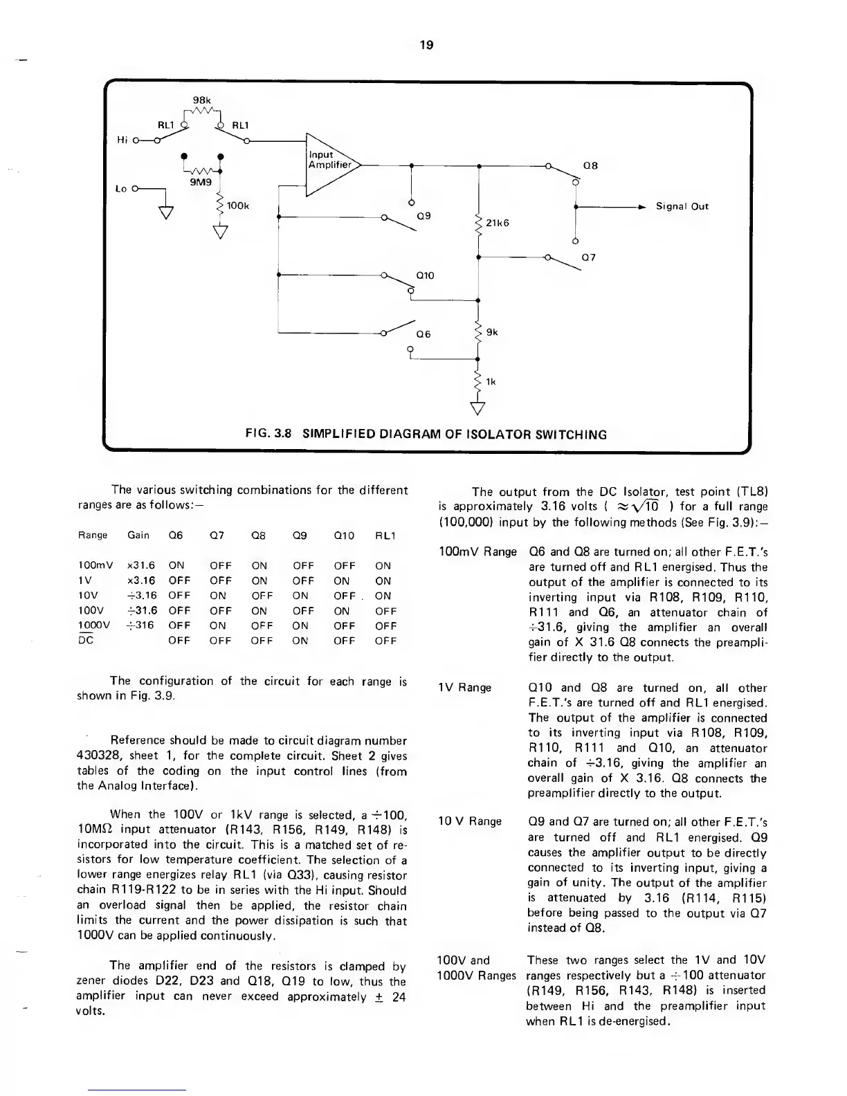
The various switching
combinations for the different
ranges are
as
follows:
—
Range
Gain Q6
Q7 Q8 Q9 Q10
RL1
lOOmV x31.6
ON
OFF
ON
OFF OFF
ON
IV x3.16 OFF OFF
ON OFF
ON ON
10V 43,16 OFF
ON
OFF
ON OFF
ON
100V
-F31.6
OFF
OFF
ON
OFF
ON OFF
1000V
4316 OFF
ON OFF
ON
OFF
OFF
DC OFF
OFF OFF
ON OFF OFF
The configuration of
the circuit for
each
range is
shown in Fig.
3.9.
Reference
should
be made to circuit diagram
number
430328,
sheet
1,
for the complete
circuit.
Sheet
2
gives
tables of the coding
on the input control
lines (from
the Analog Interface).
When the
100V or IkV range
is selected,
a
—100,
10Mi2 input
attenuator
(R143, R156,
R149, R148) is
incorporated
into
the circuit. This is
a matched
set
of
re-
sistors for
low temperature
coefficient.
The selection
of
a
lower
range
energizes relay
RL1 (via
Q33),
causing
resistor
chain R1
19-R122 to be in
series with
the Hi input.
Should
an
overload signal
then
be applied,
the resistor
chain
limits
the current
and the power
dissipation is
such
that
1000V can be applied
continuously.
The amplifier
end of
the resistors
is clamped
by
zener diodes
D22,
D23 and
Q18,
Q19
to
low,
thus
the
amplifier
input
can never
exceed
approximately +
24
volts.
The
output
from the
DC
Isolator,
test
point
(TL8)
is
approximately 3.16 volts
(
::^\/To
)
for
a
full
range
(100,000)
input
by
the following
methods (See Fig.
3.9):
—
lOOmV
Range Q6 and Q8 are turned on; all
other
F.E.T.'s
are turned
off
and RL1 energised.
Thus
the
output of the
amplifier
is
connected to
its
inverting input via
R108, R109,
R110,
R111 and
Q6,
an
attenuator chain of
^31.6,
giving the amplifier
an overall
gain of
X 31.6 Q8 connects the preampli-
fier
directly to the output.
IV Range
Q10 and Q8 are turned
on, all other
F.E.T.'s are turned off and
RL1 energised.
The
output of the amplifier
is connected
to its inverting input via
R108, R109,
R110, R111 and
Q10,
an attenuator
chain of
-^3.16,
giving
the amplifier
an
overall gain of
X 3.16.
Q8 connects the
preamplifier directly
to the
output.
10
V Range
Q9 and Q7
are turned on; all other
F.E.T.'s
are
turned off and
RL1 energised. Q9
causes the amplifier
output to be directly
connected
to
its
inverting input,
giving a
gain of
unity. The
output of
the amplifier
is attenuated
by
3.16 (R114, R115)
before
being passed
to the
output via Q7
instead of
Q8.
100V
and These two
ranges select the IV
and 10V
1000V Ranges ranges
respectively but a
-|-100
attenuator
(R149,
R156,
R143, R148)
is inserted
between
Hi
and
the
preamplifier input
when RL1 is de-energised.
 Loading...