23
3.2.3.2 A
-
D Input Control
3.2.3. 3
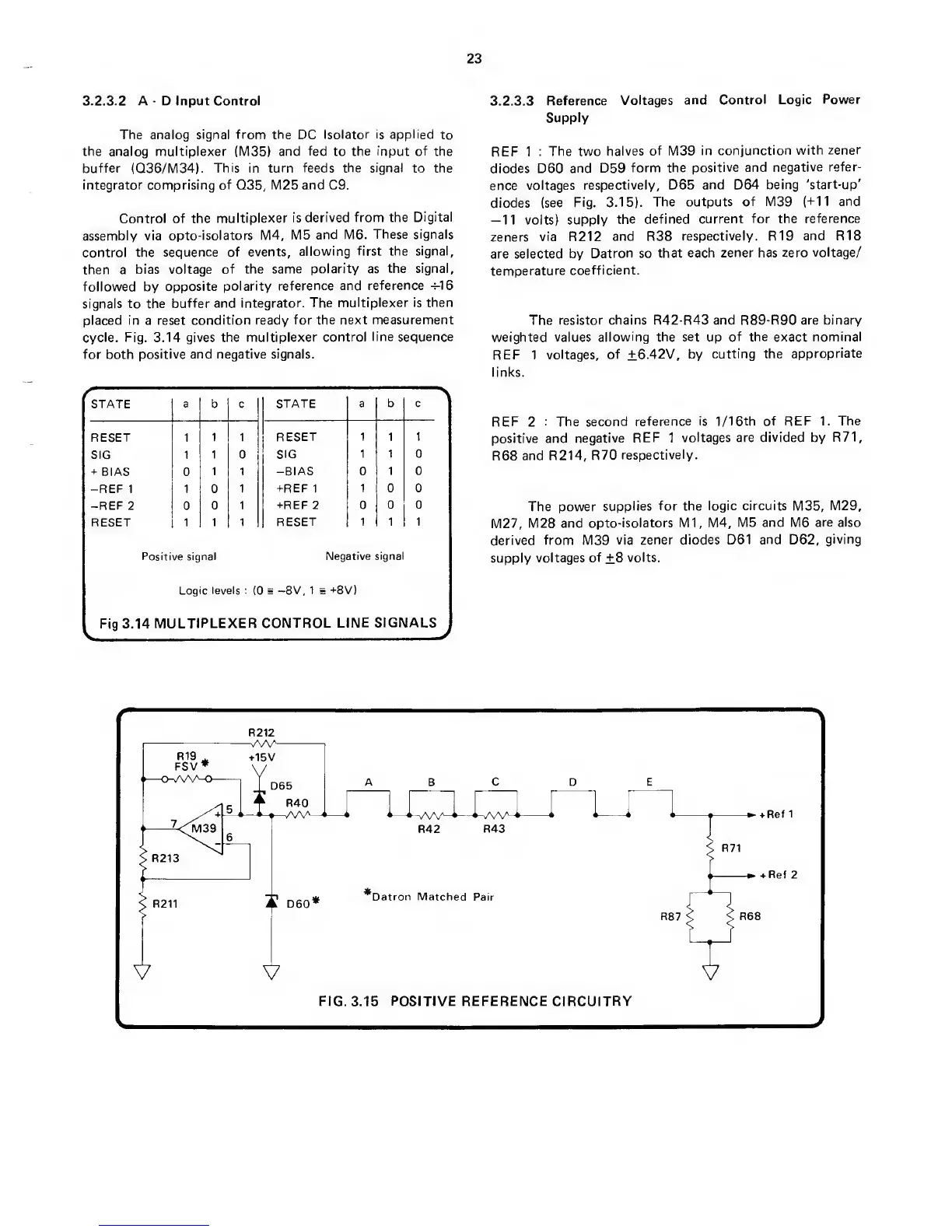
Reference
Voltages
and Control Logic
Power
Supply
The analog
signal from
the DC
Isolator
is
applied
to
the analog multiplexer (M35) and
fed
to
the input of
the
REF 1
: The two
halves
of
M39
in
conjunction with
zener
buffer (Q36/IV134).
This in turn feeds the signal
to the
diodes D60
and D59
form the
positive and
negative refer-
integrator comprising of
Q35,
M25 and C9.
ence
voltages
respectively, D65
and
D64
being
'start-up'
diodes
(see
Fig. 3.15).
The
outputs of M39 (-Ml
and
Control of the
multiplexer
is
derived from the
Digital
volts) supply
the defined
current
for
the
reference
assembly via
opto-isolators M4,
M5
and M6.
These signals
zeners
via R212
and R38
respectively.
R19
and R18
control
the
sequence
of
events,
allowing
first
the
signal,
are selected
by
Datron so that
each zener has
zero
voltage/
then a
bias voltage
of the
same polarity as
the signal,
temperature
coefficient,
followed by
opposite
polarity reference
and
reference
-r-16
signals to the
buffer and
integrator. The
multiplexer is then
placed in a reset
condition ready
for the next measurement
The
resistor
chains
R42-R43 and R89-R90 are binary
cycle.
Fig.
3.14
gives the
multiplexer control
line sequence
weighted values allowing
the set
up
of the
exact
nominal
for both
positive and negative signals.
REF 1
voltages, of
±6.
42V,
by
cutting the
appropriate
REF 2
; The second
reference is 1/16th of REF 1. The
positive and
negative
REF
1
voltages are divided by
R71,
R68
and R214,
R70
respectively.
The power
supplies
for
the
logic circuits M35, IVI29,
M27,
IV128 and
opto-isolators Ml, M4,
M5 and M6
are also
derived
from
M39
via
zener diodes
D61 and D62,
giving
supply
voltages
of
±8
volts.
f
STATE
a b C STATE
a b C
RESET 1
1 1
RESET 1 1
1
SIG
1
1 0 SIG
1 1 0
r
BIAS 0
1 1 -BIAS 0
1 0
-REF
1 1 0
1
-t-REF
1
1 0 0
-REF
2 0
0 1
HREF
2 0
0 0
RESET 1 1
1 RESET 1
1 1
Positive
signal
Negative signa
Logic levels :
(C
=
-8V, 1 s
-H8V)
^
Fig 3.14
MULTIPLEXER
CONTROL
LINE SIGNALS
J
 Loading...