35
Data Control.
Data handled
by the system consists
of
a stream of
measurement information
on which
a
number
of operations
are carried
out. A second
stream,
asynchron-
ous with the first,
consists of
commands
derived from
the front
panel
or
digital
interface,
controlling
both the
measurement circuits
and computation
programs.
Oper-
ations
on the
measurement stream
basically
consist of
acquiring
the raw data from the
A-D
converter,
calibrating
this
data and carrying
out any
other computations,
and
converting
and formatting
the
data for
output. Note that
a
job
consuming
data
is given
higher
priority than
the one
producing
data for it, allowing
a producer
to place
data
into
an empty buffer.
The consumer is
activated
by a
flag,
set
by the producer
to
indicate
data ready
in the buffer.
Process Control.
Control of
the instrument
by the
processor, initiated
from the front panel
or digital
interface,
is
arranged
by using a 'pipeline
control'
of
the
major
system
state and a 'first in/first
out' buffer
between
the
interrupt level
routine receiving
the control
command
and
the main
program implementing it.
The
major system
state
consists of
the range,
function, resolution,
filter,
ratio,
autorange, etc., flags
and the
computation
mode (reading,
A-B,
-f-C,
etc.). The pipeline
comprises
three levels.
The
top,
level
1,
reflects
the state being
programmed,
the second,
level
2,
the state of
the measurement
circuits
and the
third,
level
3,
the
measurement being
processed.
When
a
command is input, level
1 is
updated (e.g.
a new range
is
selected)
and as soon
as the measuring
circuits
are
not
converting
an input signal,
the state in level
1 is
moved to
level
2 causing
the measurement
circuits
to update
to the
/
"
new state. When an
A-D conversion is
complete,
data
is
read from the A-D
and
the
state transferred
from level
2 to
3,
providing information for
the processing
routines.
Additionally, at this time,
the
level
1 to level
2 transfer is
repeated
and the measurement
circuits again
updated to
allow for commands
received while
the conversion is in
progress.
A second control
mechanism
used is to input
all the
commands via
a
'first in/first
out'
buffer
between
the
interrupt level
routine receiving
the command
and the
main program implementing
it.
Thus the
processor under
remote control is able
to
'simultaneously'
set up the
requirements for
the next reading,
convert
the
current
reading and
process the last one.
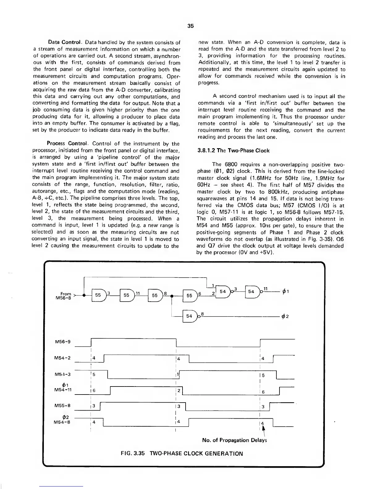
3. 8.
1.2
The Two-Phase
Clock
The
6800 requires a non-overlapping
positive
two-
phase
(01,
02)
clock. This is
derived from
the line-locked
master clock
signal (I.SMHz for
50Hz
line, 1.9MHz for
60Hz
-
see sheet
4).
The first
half of
M57 divides the
master clock
by two to 800kHz,
producing
antiphase
squarewaves
at
pins
14 and
15.
If
data
is
not being
trans-
ferred via
the CMOS data bus;
M57
(CMOS I/O) is at
logic
0,
M57-11 is
at
logic
1,
so M56-8 follows
M57-15.
The
circuit
utilizes
the propagation delays
inherent in
M54 and M55 (approx.
10ns
per
gate), to ensure
that the
positive-going
segments of Phase 1
and Phase
2
clock
waveforms
do
not overlap
(as
illustrated in Fig.
3-35). Q6
and Q7
drive
the clock output at voltage levels
demanded
by the processor
(OV
and
-t5V).
\
M56-9
IVI54-2
M51-3
01
M54-11
I5
16
I
5
M55-8
02
M54-8
|3
No.
of Propagation Delays
FIG.
3.35 TWO-PHASE
CLOCK
GENERATION
V.
 Loading...