48
3.13
REAR (POWER
SUPPLY)
PCB
ASSEMBLY
(Circuit Drawing
No. 430295)
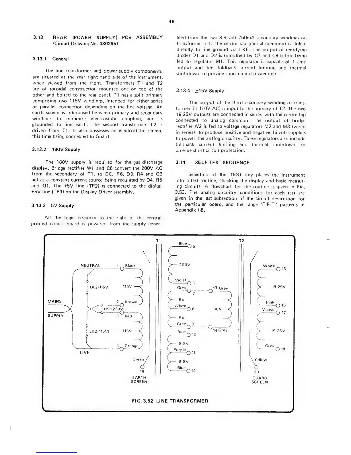
3.13.1
General
The
line
transformer
and
power
supply
components
are situated
at the
rear right
hand side
of the instrument,
when viewed from the from. Transformers
T1 and T2
are of toroidal construction mounted one on
top
of
the
other and bolted
to
the
rear panel. T1 has
a
split primary
comprising two
115V
windings, intended
for either series
or
parallel
connection depending
on
the line
voltage. An
earth screen is interposed
between
primary
and secondary
windings
to
minimise
electrostatic coupling,
and is
grounded
to
line earth.
The
second
transformer
T2 is
driven fiom
T1 It also
possesses
an electrostatic
screen,
this
time
being
connected
to
Guard.
3.13.2 180V
Supply
The
180V supply is required for the gas discharge
display. Bridge rectifier
W1 and
C6
convert the
200V
AC
from the
secondary
of
T1,
to DC.
R6,
D3, R4
and
Q2
act
as a constant current
source being regulated
by D4, R5
and
Q1.
The
+5V
line
(TP2I
is
connected to the digital
+5V
line
(TP3)
on the Display Driver
assembly.
3.13.3 5V Supply
All
the logic circuitiy
to
the right of
the central
printed circuit
board
is powered from
the supply gener
ated from
the two
8.8
volt
750mA
secondary windings on
transformer
T1.
The centre
tap
(digital
common) is linked
directly
to
line ground
via
LK6.
The
output of rectifying
diodes
D1
and
D2 is smoothed by
C7
and
C8
before being
fed
to regulator Ml. This regulator
is capable
of 1 amp
output and
has
foldback current limiting
and thermal
shut-down,
to
provide short circuit
protection.
3.13.4
i15V
Supply
The
output
of
the third secondary
winding of
trans-
former
T1 (10V
AC) is input
to the
primary
of T2. The
two
19.25V outputs
are connected
in series, with the
centre tap
connected
to
analog
common. The output
of bridge
rectifier
W2
is fed
to
voltage
regulators M2
and M3 (wired
in series),
to
produce
positive and negative
15 volt supplies
to power the analog circuitry. These
regulators
also include
foldback current
limiting
and thermal
shut-down,
to
provide short-circuit
protection.
3.14 SELF TEST
SEQUENCE
Selection
of the
TEST key
places
the instrument
into
a test routine, checking
the display
and
basic
measur-
ing
circuits.
A flowchart for
the routine
is given
in
Fig.
3.53. The analog
circuitry
conditions
for
each
test are
given
in the last
subsection
of the circuit
description
for
the particular
board, and
the range
'F.E.T.'
patterns
in
Appendix
1-8.
 Loading...