53
Analog
Assembly
(A-D Converter)
23. Select
100V
range
and
apply short
circuit
between
Hi and
Lo. Connect
DVM Hi
to
TP7,
Lo to TP20.
If
reading is +6.
42V +0.03V proceed
to step
25.
24.
Switch off
instrument
and make positive
reference
links B
& C,
if
cut i.e. the links
alongside TP7.
Switch
on instrument and
measure voltages
on TP7
once
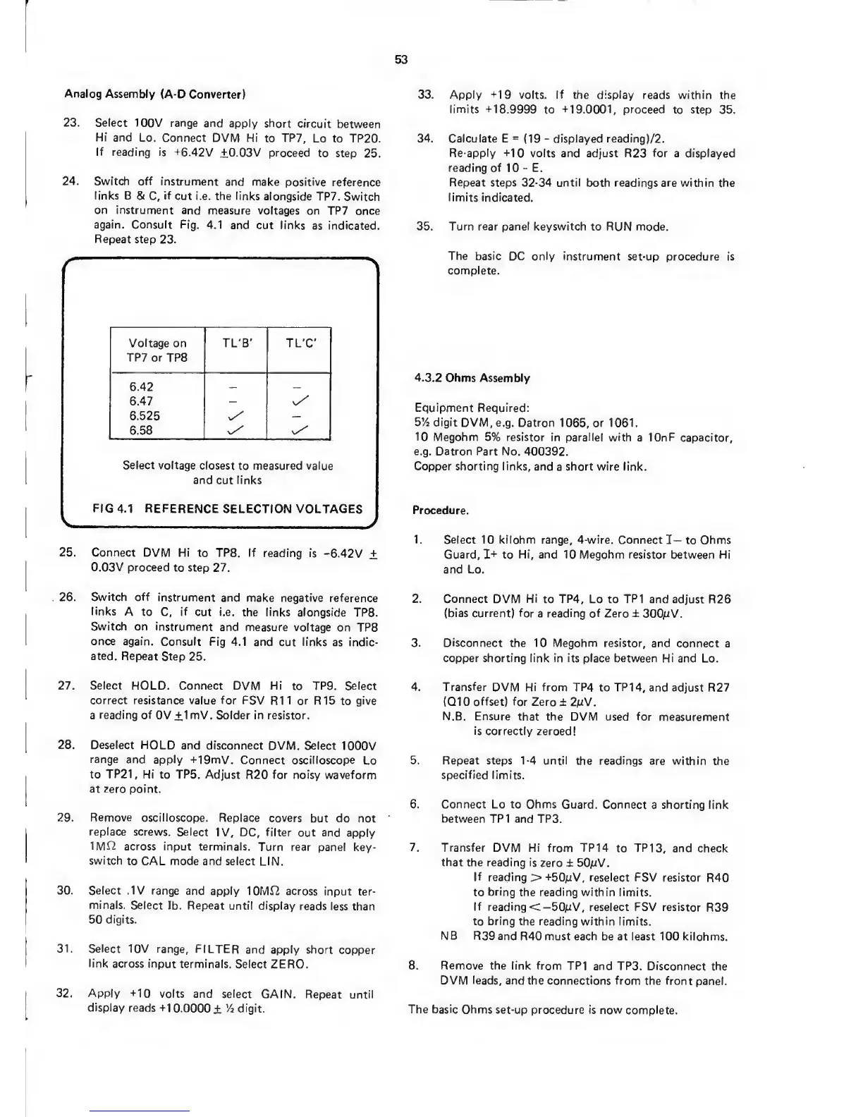
again. Consult Fig.
4.1
and cut links
as indicated.
Repeat
step 23.
Voltage
on
TP7
or TP8
TL'B'
TL'C'
6.42
6.47
6.525
v/
—
6.58
Select
voltage
closest
to
measured
value
and
cut
links
FIG
4.1 REFERENCE
SELECTION
VOLTAGES
V
/
25. Connect
DVM Hi
to TPS.
If
reading is
-6.42V
±
0.03V proceed
to step 27.
26.
Switch off
instrument
and
make negative reference
links
A
to C,
if
cut i.e.
the links alongside
TPS.
Switch on
instrument
and measure voltage
on TPS
once again.
Consult Fig
4.1 and
cut
links
as indic-
ated. Repeat
Step
25.
27. Select
HOLD. Connect DVM Hi
to
TP9. Select
correct resistance value for
FSV
R11
or
R15 to
give
a
reading of
OV +1mV. Solder in resistor.
2S.
Deselect
HOLD
and disconnect
DVM.
Select
1000V
range
and apply
-M9mV.
Connect oscilloscope
Lo
to TP21,
Hi to TP5.
Adjust
R20
for
noisy waveform
at zero
point.
29.
Remove
oscilloscope.
Replace covers
but
do
not
replace
screws.
Select IV,
DC,
filter
out
and
apply
1Mf2 across
input terminals.
Turn rear panel
key-
switch
to CAL
mode
and select
LIN.
30. Select .IV
range and apply
10MJ2 across
input ter-
minals.
Select
Ib.
Repeat until
display
reads less than
50
digits.
31.
Select 10V range,
FILTER
and apply
short copper
link across
input terminals.
Select
ZERO.
32. Apply
-t-10
volts and
select
GAIN. Repeat until
display
reads
-H 0.0000
±
%
digit.
33. Apply -M9 volts. If
the
display
reads within
the
limits
-t-18.9999
to
-t19.0001,
proceed
to step
35,
34. Calculate E
=
(19
-
displayed reading)/2.
Re-apply
-HO volts and adjust R23
for
a displayed
reading of
10
-
E.
Repeat
steps
32-34
until both readings are
within
the
limits indicated.
35. Turn rear panel
keyswitch to RUN mode.
The basic
DC only instrument
set-up procedure is
complete.
4.3.2 Ohms Assembly
Equipment
Required:
5’/j
digit
DVM, e.g.
Datron
1065,
or
1061.
10 Megohm
5% resistor in parallel with
a
lOnF
capacitor,
e.g. Datron Part
No. 400392.
Copper
shorting links, and
a short wire link.
Procedure.
1.
Select
10 kilohm range, 4-wire. Connect
I—
to
Ohms
Guard,
I-i-
to Hi, and 10 Megohm resistor
between
Hi
and Lo.
2. Connect DVM
Hi
to
TP4,
Lo to
TP1
and adjust
R26
(bias current) for
a reading of Zero ±
300pV.
3. Disconnect
the 10 Megohm resistor, and
connect a
copper
shorting
link
in its place between Hi
and Lo.
4. Transfer
DVM Hi from TP4
to
TP14,
and adjust
R27
(01
0
offset)
for Zero
± 2pV.
N.B. Ensure that the
DVM used
for
measurement
is
correctly zeroed!
5. Repeat steps
1-4
until
the
readings
are within
the
specified limits.
6. Connect
Lo to Ohms Guard.
Connect
a
shorting link
between TP1 and TP3.
7.
Transfer
DVM Hi from TPM
to
TP13,
and check
that the reading
is zero
± 50/jV.
If
reading
>
-^50/iV,
reselect FSV resistor
R40
to
bring
the reading within limits.
If
reading
C—50
aiV,
reselect
FSV resistor
R39
to
bring the
reading within limits.
NB
R39 and R40must
each be at least 100 kilohms.
8. Remove
the link from TP1
and TP3.
Disconnect the
DVM
leads,
and
the connections from
the front panel.
The basic
Ohms set-up procedure is
now complete.
 Loading...