54
4.3.3
OPTION 10 AC Assembly
Equipment Required:
5mV/Div oscilloscope, e.g. Telequipment
D83.
5Yi digit
DVM
with
Ohms.
e.g.
Datron
1065,
1061
.
DC calibrator, e.g.
Datron 4000 or
4000A.
AC calibrator,
e.g. Datron 4200.
Asymmetric signal, IV
RMS, Crest Factor 5:1
±0.02%,
reversible
polarity.
Procedure
1. Select AC 1000V
range
and HOLD.
Short Hi
to Lo.
Connect DVM Hi to TL7, Lo to
TP8 and note read-
ing.
Select 1V
range
and adjust
R121 (bias current)
to
give same reading
±10,uV.
2.
Select
lOOmV
range,
AC
+
DC
and
adjust
R112
(offset
adjust)
for
an
indication of
zero
±50uV
on
the DVM.
3.
Repeat steps 1. and
2.
until readings are within
the
specified limits.
4. Select
10V
range and
HOLD.
Connect oscilloscope
Hi
to TPS, Lo
to
TPS and
adjust
R90 (rectifier
zero)
for maximum noise
about zero. Remove the oscillo-
scope.
5. Connect
DVM Hi
to
TP2,
Lo to
TPS
and adjust
R75 (linearity)
for an indication
on the DVM of
1.8mV±10%.
6. Select
AC, IV
range,
FILTER
and
apply
IV 500Hz.
Connect
DVM Hi
to TL5,
Lo to TPS.
If
reading is
+3.
157V ±0.01V proceed
to
step
8.
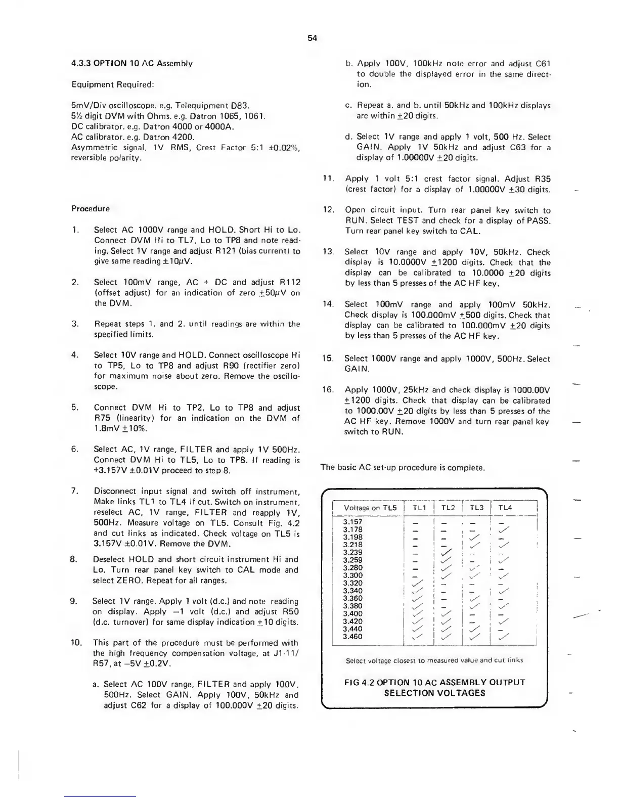
7. Disconnect input
signal
and switch
off
instrument.
Make links
TL1 to
TL4
if
cut. Switch
on instrument,
reselect
AC,
IV
range,
FILTER
and reapply
IV,
500Hz. Measure
voltage on
TL5. Consult
Fig.
4.2
and
cut
links
as indicated.
Check
voltage
on TL5 is
3.157V ±0.01V. Remove the
DVM.
8.
Deselect HOLD and short circuit instrument Hi and
Lo.
Turn
rear panel key
switch
to
CAL mode and
select ZERO. Repeat for all ranges.
9.
Select IV
range. Apply 1 volt (d.c.) and note reading
on
display. Apply
—1
volt (d.c.)
and
adjust R50
(d.c.
turnover) for
same
display indication
±10
digits.
10.
This
part of the procedure
must be performed with
the high frequency compensation voltage,
at Jl-ll.^
R57,at -5V
±0.2V.
a.
Select
AC 100V
range, FILTER
and apply 100V,
500Hz.
Select GAIN. Apply 100V, 50kHz and
adjust C62
for
a
display
of 100.000V
±20
digits.
b.
Apply
100V, 100kHz note error
and adjust
C61
to double the displayed
error
in
the same direct-
ion.
c. Rep>eat
a.
and
b.
until 50kHz
and
100kHz
displays
are within
±20
digits.
d.
Select IV range
and apply 1 volt,
500
Hz. Select
GAIN. Apply
IV 50kHz
and adjust
C63
for
a
display of
1.00000V
±20
digits.
11. Apply
1 volt 5:1
crest factor signal.
Adjust R35
(crest
factor) for
a display of
1.00000V
±30
digits.
12. Open circuit
input. Turn rear panel
key
switch to
RUN. Select
TEST and
check
for
a display
of PASS.
Turn rear
panel
key
switch
to CAL.
13. Select
10V
range and apply
10V, 50kHz. Check
display
is
10.0000V ±1200
digits.
Check
that the
display can
be calibrated
to
10.0000
±20
digits
by
less
than
5
presses of
the AC HF key.
14. Select
lOOmV range
and apply
lOOmV 50kHz.
Check display
is
lOO.OOOmV +500 digits.
Check that
display
can
be calibrated
to lOO.OOOmV
±20
digits
by less
than
5
presses of the
AC
HF
key.
15. Select
1000V range and apply
1000V, 500Hz.
Select
GAIN.
16.
Apply
1000V,
25kHz and
check
display
is
lOCXD.OOV
±1200
digits. Check
that
display
can
be calibrated
to
1000.00V
±20
digits
by less than
5
presses of
the
AC
HF key. Remove
1000V and turn rear panel
key
switch to
RUN.
The basic
AC set-up procedure is
complete.
>.
Voltage
on
TL5 TL1 ! TL2
1
TL3
TL4_
1
3.157
1
_
,
3.178
1
_
>
3.198
_
3.218
_
1
3.239
i
3.259
_
3.280
!
v/
3.300
•
^ y
3.320
i
_
3.340
{
_
~y
3.360
v/
3.380
y
1
3.400
__
3.420
v/
1
v/
;
3.440
i
3.460
-
v/
Select voltage
closest to
measured
value and cut
links
FIG
4.2
OPTION
10 AC
ASSEMBLY
OUTPUT
SELECTION
VOLTAGES
V
y
 Loading...