55
4.3.4 OPTION 12 AC Assembly
Equipment Required:
5mV/Div oscilloscope, e.g. Telequipment
D83.
5'A
digit
DVM
with
Ohms. e.g. Datron 1
065,
1061.
DC calibrator, e.g. Datron 4000 or
4000A.
AC calibrator, e.g. Datron
4200.
Asymmetric
signal, IV RMS, Crest Factor 5:1
±0.02%,
reversible polarity.
CAUTION
The
following
procedures should commence with
the HF
Autocal voltage close
to
the center of its
span. To check
this, select
the
100V
AC
range and measure the
DC
voltage
at J1-11
with
respect to TPS. If it
is
between
+4V
and
+6V,
it is
NOT necessary to clear the calibration
stores.
If
outside
these limits, the cal stores
should be cleared as
described in
para 4.3.1 operations
(13),
(14)
and
(15).
CLEARING THE
CAL STORES ENTAILS
A FULL
'AUTOCAL' OF THE INSTRUMENT!
Before
proceeding; ensure
that at least the Analog
Assembly
LIN and
Autocalibrations have been carried
out.
AC Preamplifier
Zero
1. Read
and comply with the CAUTION above.
2. Apply
short circuit input. Select
AC
+
DC, lOOmV
range
and
HOLD.
3. Connect DVM
Lo to
TPS, Hi
to
Test link
K (TLK).
Adjust
R14S
(bias
current)
for
a reading of zero,
±140pV.
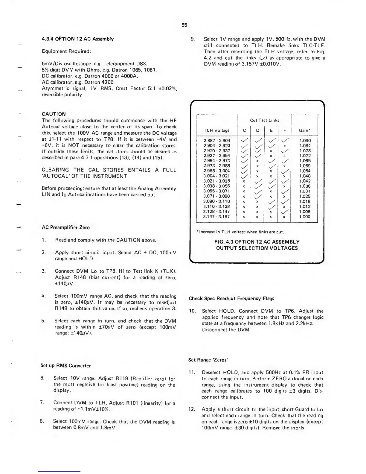
9.
Select
IV range and
apply IV, 500Hz, with
the
DVM
still
connected to TLH.
Remake links
TLC-TLF.
Then
after
recording the TLH voltage, refer
to
Fig.
4.2 and
cut
the
links
{^)
as appropriate
to
give
a
DVM reading
of
3.157V ±0.010V.
TLH Voltage
Cut
Test Links
Gain*C D E
F
2.887
•
2.904
x/
v/ s/
v/
1.090
2.904
-
2.920
n/
v/
v/
X
1.084
2.920
-
2.937
n/ v/
X
v/
1.078
2.937
-
2.954
v/
s/
X X 1.072
2.954
2.973
s/
X
v/
1.065
2.973
-
2.988
X
v/
X
1.059
2.988
-
3.004 X X
v/
1.054
3.004-3.021
v/
X X X 1.048
3.021
-
3.038 X
s/ x/
1.042
3.038 3.055 X
v/
X
1.036
3.055-3.071 X
x/
X
v/
1.031
3.071
-
3.090
X
v/
X X 1.025
3.090
-
3.110 X X
v/
1.018
3.110-3.128
X X
v/
X
1.012
3.128-3.147
X X X
v/
1.006
3.147
-
3.167 X X X
1.000
’Increase in TLH voltage when
links are cut.
FIG.
4.3
OPTION
12
AC ASSEMBLY
OUTPUT SELECTION
VOLTAGES
4.
Select
lOOmV range
AC, and check that
the reading
is
zero, ±140/:tV. It
may be necessary to re-adjust
RMS to obtain this value. If
so,
recheck
operation
3.
5. Select each
range in turn, and
check that the
DVM
reading is within
±70pV of zero
(except lOOmV
range:
±140pV).
Check
Spec Readout
Frequency Flags
10.
Select
HOLD. Connect
DVM to TP6.
Adjust
the
applied frequency
and note that
TP6
changes
logic
state at
a
frequency between I.SkHz and 2.2kHz.
Disconnect
the
DVM.
Set up RMS
Converter
6.
Select
10V range.
Adjust
R119 (Rectifier
zero) for
the
most negative
(or
least positive)
reading
on the
display.
7.
Connect
DVM to TLH.
Adjust R101
(linearity)
fora
reading
of
+1.1mV±10%.
8. Select
lOOmV
range.
Check
that the
DVM
reading is
between
O.SmV
and
I.SmV.
Set
Range ‘Zeros'
11. Deselect
HOLD,
and apply 500Hz
at
0.1% FR input
to each range
in
turn.
Perform
ZERO
autocal
on each
range, using the instrument display
to
check that
each range calibrates to 100 digits
±3
digits. Dis-
connect the input.
12. Apply a short circuit
to
the input, short
Guard to
Lo
and
select each range
in turn. Check that the
reading
on each range is zero
±10
digits
on the
display
(except
lOOmV range
±30
digits). Remove the
shorts.
 Loading...