EasyManuals Logo

Davies Craig EWP150 User Manual

Default Icon
12 pages
To Next Page IconTo Next Page
To Previous Page IconTo Previous Page
Page #6 background imageLoading...
Page #6 background image
Page 6 of 12
1. BLUE CONNECTOR
2
. SELF TAPPER
3
. SCTOCHLOCK
4
. RING TERMINAL
5. FUSE HOLDER & FUSE
3
THERMAL SWITCH
IGNITION
RED
YELLOW
BLACK
ORANGE
BATTER
Y
+VE
4
FUS
E
RED
FUS
E
5
5
EARTH
PUMP
MOTOR
RELAY
BLACK
BLUE
GREEN
2
86
30
87
85
1
1
1
OPTION 2: USING THE EWP
®
AS A BOOSTER PUMP
Part #0401 or Part #0444
NOTE: This option when combined with a Davies, Craig Thermatic
®
Switch,
Part #0401 or Part #0444, will turn the EWP
®
on at the temperature you set,
to give additional flow to an overheating cooling system.
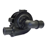
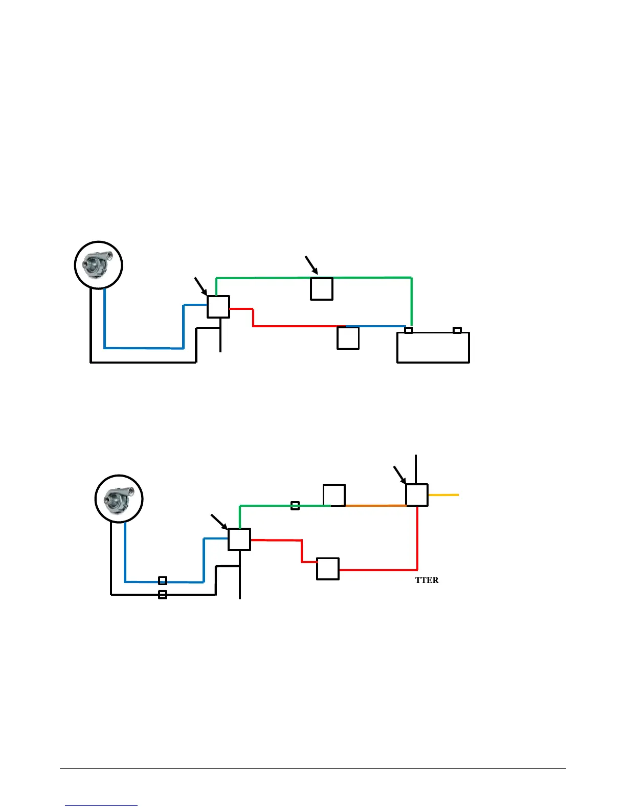
INSTALLING THERMAL SWITCH (Part #0401 OR #0444)
1. Install the Thermo Switch (Part #0401 or Part #0444) - Refer Wiring Diagrams
(Figure 1 and Figure 2) below.
2. For detailed instructions on installing switches, please refer to 0401 & 0444
instruction sheets.
3. Bleed the EWP
®
. Refer to SECTION 4: BLEEDING THE EWP
®
(Page 9). After
bleeding the EWP
®
continue on with the next stage.
WARNING: ENSURE IGNITION SOURCE IS NOT CONNECTED TO THE ENGINE MANAGEMENT SYSTEM
2
Figure 1: Wiring Diagram: EWP® With Thermal Switch - Part #0401
Figure 2: Wiring Diagram: EWP® with Thermal Switch - Part #0444
THERMAL SWITCH
BATTERY
FUSE
EARTH
PUMP MOTOR
RELAY & LOOM
FROM PUMP
PACKAGING
+
_
BLACK
BLUE
RED
GREEN
BLUE

Questions and Answers:

Question and Answer IconNeed help?

Do you have a question about the Davies Craig EWP150 and is the answer not in the manual?

Davies Craig EWP150 Specifications

General IconGeneral
BrandDavies Craig
ModelEWP150
CategoryWater Pump
LanguageEnglish

Related product manuals