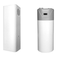
The Dayliff HPW All in One Heat Pump is a domestic water heating system designed for high-efficiency heat pump technology. It integrates a heat pump with an efficient heat exchanger, generating heat from ambient air through an evaporation/condensation cycle. The system stores heated water in a stainless steel tank with an internal enamel coating and a magnesium anode for cathodic protection against corrosion. The tank is lined with high-grade thermal insulation for heat retention.
Function Description
The HPW heat pump system provides domestic hot water by utilizing ambient air as a heat source. It operates on an evaporation/condensation cycle, transferring heat to the stored water. The system includes an integral heat pump fitted on top of the hot water cylinder, a GMCC compressor with a Coefficient of Performance (COP) of up to 4.16 (at 20°C ambient temp, 15°C water temp), and a suitable hot water temperature of up to 75°C. It also features a tube-type heat exchanger coiled externally around the water tank for performance and safety, an inbuilt sterilizing function, and an integral 2kW electric heating element for temperature boosting. The system includes a digital controller for operational and timer settings, and fault indication. It is supplied with an ozone-friendly R134A refrigerant gas for optimal performance.
Important Technical Specifications
The Dayliff HPW heat pumps are available in three models: HPW150, HPW200, and HPW300, with varying water tank volumes and heating capacities.
- Water Tank Volume:
- HPW150: 150 Liters
- HPW200: 200 Liters
- HPW300: 300 Liters
- Heating Capacity:
- HPW150: 2.5 kW
- HPW200: 2.5 kW
- HPW300: 2.5 kW
- Rated/Max Input Power:
- HPW150: 0.6/3 kW
- HPW200: 0.6/3 kW
- HPW300: 0.6/3 kW
- Fan Flow:
- HPW150: Side
- HPW200: Top
- HPW300: Top
- Rated/Max Current:
- HPW150: 2.7/15 A
- HPW200: 2.7/15 A
- HPW300: 2.7/15 A
- Inlet/Outlet: 3/4" for all models
- Net Dimensions (mm):
- HPW150: 500x500x1670
- HPW200: 620Diax1638
- HPW300: 620Diax2038
- Net Weight (kgs):
- HPW150: 92
- HPW200: 105
- HPW300: 130
- Power Supply: 220V/50Hz for all models.
- Min. Cable Diameter (mm²): ≥2.5 (continuous length <30m)
- Ground Wire: ≥ø1.0mm
- Manual Switch (A): Capacity ≥20, Fuse 20
- Leakage Protection Device: Below 30mA, 0.1 sec
- Maximum Outlet Water Temperature: 60°C.
Usage Features
The heat pump is designed for ease of use with a digital controller that displays various operational parameters and allows for setting adjustments.
- Control System Specifications:
- Operating Condition: Voltage: 220V ±10%, 50Hz±1Hz. Ambient temperature: -7 ~ +43°C. Storage temperature: -20 ~ +75°C. Relative humidity: 0 ~ 95%RH. Temperature accuracy: ±1°C.
- Main Function: Displays temperature and setting temperature, ambient temperature, exhaust temperature, and so on. Power cut memory function. Timing on/off. Automatic defrosting. Forced defrost. Error code display and query. Key-Lock Function. Anti-freezing function. Automatic system run in absence of a wire controller or if faulty.
- Installation:
- The unit should be reliably earthed.
- It is a household appliance and requires protection against electric fault.
- Labels or parameter plates should not be removed.
- Installation and maintenance should be carried out by qualified professionals.
- Any modification or improper repair is not advised.
- Ensure electrical supply is compatible with the rated current value (not less than 10A).
- Install in a cool, dry place, well ventilated and away from children. The power plug should be installed about 1.8m above ground for safety.
- Do not install indoors to avoid overflow, noise, or high temperature.
- Ensure sufficient space for installation and maintenance.
- Ensure inlet or outlet airflow is not obstructed.
- Install on a flat surface that can bear the weight and is easy to install vertically. The surface should not increase noise or vibrations.
- Avoid high temperature, saline conditions, and long-term exposure to harsh elements.
- Do not install in kitchens where there is cooking gas and oil spills.
- Do not touch the fan with hands or other objects.
- Equipment provides complete isolation between water and electricity for safety.
- The condenser coil is wrapped around the stainless tank, not in direct contact with water.
- Flexible installation is achieved by varying air inlet and outlet duct piping.
- Heat pumps should be installed outdoors. If installed indoors, sufficient air circulation is required. The air duct total length should be equal to or less than 6 meters, and the duct diameter should be equal to or more than 150 mm.
- Water-resistant measures must be taken if installed outdoors.
- An air filter should be installed at the inlet to trap air debris.
- Use CPVC, PPR, or UPVC pipe for connections; do not use iron pipe.
- Water pipes should have a life not less than the heat pump's life.
- Install a G1/2'', 8bar relief valve, ensuring the drainage pipe is not blocked.
- Keep the safety valve handle free and drainage port clear of debris.
- After pipeline setup, open cold and hot water valves to fill the tank.
- A booster pump may be installed if intake pressure is below 1.5 Bar. A relief valve must be installed if intake pressure is greater than 6.5 Bar.
- Ensure proper drainage for condensed water droplets.
- First Time Operation:
- Ensure the tank is full of water before connecting the unit with power.
- Operating without water in the tank may damage the auxiliary E-heater.
- The LCD screen will light up when powered on, ready to receive commands.
- Water temperature over 50°C can cause severe burns; children, disabled, and elderly should be protected. Water temperature limiting values are recommended.
- Water draining: Drain water from the heater before cleaning or moving the unit.
- Control System:
- The controller displays the current status of the heat pump (on/off, cooling, heating, auto, needs repair, defrosting, electric heater, water temperature, inlet/outlet temperature, timer functions).
- Buttons for Power/Exit, Up, Down, Mode, Time, and Set allow for controlling the unit, setting temperatures, timers, and accessing parameters.
- Button combinations allow for quick heating, defrosting, and resetting factory parameters.
- Set Water Temperature:
- In manual mode, press "∧" or "∨" to enter the water temperature setting state.
- Press "∧" or "∨" to increase or decrease the water temperature.
- In automatic mode, press "∧" or "∨" to enter the automatic temperature adjustable parameter setting.
- Real Time Clock Settings:
- Press "M" + "G" to enter the real-time clock setting interface.
- Press "∧" or "∨" to set the hour on the clock.
- Press "Time" button to set minutes.
- Press "G" button to confirm settings.
- Programmed Function Settings:
- Three pre-determined time spans for working sequence.
- Enable/disable the working mode.
- Switch between the hour and minute of the three time slots.
- "ON" or "OFF" symbol will flash to indicate increase or decrease.
- Cooling/Heating Mode:
- Switch between cooling or heating mode using the "M" button.
- The compressor is allowed to start running after at least 3 minutes of stopping.
- Forced Speed Heating:
- The heat pump needs to be in the working period after the timing control is enabled.
- The current heating mode is met and the temperature condition for continued heating is satisfied.
- Press "M" + "∧" button for more than 5 seconds to activate/deactivate the "speed heating" function.
- Forced Defrosting:
- Press "M" + "∨" button for more than 5 seconds to activate or deactivate the "Defrost" function.
- Forced Sterilization:
- Press "M" + "∧" + "∨" button for more than 5 seconds to activate or deactivate the "sterilization" function.
- Return Water Time Setting (Fluorine Cycle Unit):
- Press and hold the "G" button for 3 seconds in the main interface to enable/disable the timed water return mode.
- The timed water return mode is enabled, the timed return time setting is entered.
- The corresponding parts are flashed and the "ON" or "OFF" symbol is flashing.
- Press "∧" or "∨" to increase or decrease the value.
- Press "G" button to exit the modification and return to the normal display state.
- The factory default return water time is as follows: A, time period 1 opening time: 6:30, B, time period 1 closing time: 7:30, C, time period 2 opening time: 18:30, D, time period 2 closing time: 22:30.
- Query Running Status:
- Press "M" + "∧" or "∨" button for more than 3 seconds to enter the running status query interface.
- Press "G" button to check each operating condition.
- After entering the view mode, the last viewed data code (default is "00" after power-on) and its corresponding value are displayed.
- Press "∨" button to scan the status.
- Key Lock:
- The controller is locked in normal display state if no button operation for more than 60 seconds. Press any button to unlock.
- Electric Heater Control:
- At heating mode, when the water tank temperature is ≤ set temperature -20°C, the electric heater starts.
- When the water tank temperature is ≥ the set temperature, the electric heater is turned off.
- Circulating Pump Control (Water Circulation Heat Pump):
- When defrosting, the water pump is forced to run.
- When cooling or heating, it is turned on 10 seconds before the compressor and stops 30 seconds after the compressor.
- Antifreeze Mode:
- When the controller is powered on, whether the heat pump is off or on, when the ambient temperature is too low, the water pump will enter antifreeze mode to prevent the circulation line or the water tank from freezing.
- The specific conditions for enabling and disabling the environment for low temperature antifreeze are as follows:
- When the ambient temperature is ≤ 2 °C, and the duration of the circulating water pump is off for more than 30 minutes, the circulating water pump is forcibly started for 60 seconds.
- When the ambient temperature rises to ≥ 4 °C, the antifreeze mode is disabled.
- When the ambient temperature sensor is faulty, it is mandatory to start the circulating water pump periodically, and run for 60 seconds every 30 minutes.
- Circulation Pump Control (Optional: Fluorine Cycle Heat Pump):
- When the controller is in the normal display state, click the "G" button to start the manual water circulation function.
- The manual return water control is as follows:
- No Pipe Temperature Sensor: When the manual return water function is activated, the water pump is started. After 30 seconds, the buzzer sounds three times, prompting the user to use the hot water; after 30 seconds, the "G" All In One Heat Pump For Domestic Hot Water - 28 - icon flashes 3 times and the buzzer sounds for 3 seconds. Turn off the water pump and the "G" icon goes out (if the timed water is set before, the "Back Pump" and "Timer" icons are displayed). During this process, press and hold the "cold and hot" button for 1 second to manually cancel the manual water return function.
- Pipe Temperature Sensor Installed: When the manual return water function is activated, if the return water pipe temperature is <35°C (default 35°C), and the current water tank temperature ≥ return water set temperature + return water temperature difference, return water pump will starts. If the return water pipe temperature ≥ back water set temperature + return water temperature difference for 5 seconds or temperature control return water time ≥ 2 minutes, the buzzer sounds three times, prompting the user to use hot water; after 30 seconds, the "G" icon flashes 3 times, buzzing the device will beep for 3 seconds, the water pump will be turned off, and the "G" icon will be off (if the timed water is previously set, the "Back Pump" and "Timer" icons will be displayed).
- Timed Return Water:
- When the controller is in the normal display state, press and hold the "G" button for 3 seconds to start or turn off the timed water return function; the "G" icon lights up when it is turned on, and the "G" icon turns off when it is turned off.
- The timing return control is as follows:
- No Return Water Temperature Sensor: When the timing water returned function is activated and the timed start time is reached, the water pump is started. After 30 seconds, the water pump is turned off, and the buzzer sounds three times, prompting the user to use the hot water; After 15 minutes, the water pump is started again and the cycle is repeated. If press and hold the "cold hot" button for 1 second or the timed return water close time is reached in this process, the timed water return function will be turned off (the return water function is still valid for next time, unless the timed return function is turned off).
- Return Water Temperature Sensor Intalled: When the timing return water starts, and the start time reaches, if the return water pipe temperature < return water set temperature, and the current water tank temperature ≥ return water set temperature + return water temperature difference, the return water pump will start. If backwater pipe temperature ≥ return water set temperature + return water temperature difference for 5 seconds or temperature control return water time ≥ 2 minutes, the water pump will turn off. The buzzer sounds three times, prompting the user to use hot water; When the pipe temperature < return water set temperature, the water pump return is started again and the cycle is repeated. If press and hold the "cold hot" button for 1 second or the timed return water close time is reached in this process, the timed return function will be turned off (the return water function is still valid for next time, unless the timed return function is turned off).
- When the return water temperature is faulty, it will automatically switch to the "no return water temperature sensor" mode.
- Anti-fouling Function:
- The return pump/circulation pump stops for a long time, the pump will be rusted or scaled, and the pump needs to be started periodically.
- After the pump has been on standby for 12 hours, it is forced to run for 1 minute.
- High Temperature Sterilization Control for Electric Heater:
- While the controller is in normal display state, press and hold the "M" "∧" "∨" button for more than 5 seconds at the same time, the heater symbol flashes to indicate that it enters the manual sterilization mode.
- At this time, the electric heater is started to heat the water to 75°C and the water temperature is maintained at 70 to 75°C for 30 minutes, then the sterilization mode will be automatically exited.
- After starting the manual sterilization function, press and hold the "M" "∧" + "∨" button for 5 seconds or more at the same time to exit the manual sterilization mode.
- When the water temperature setting value is ≥75°C, the sterilization function is not activated.
- Automatic Sterilization Mode:
- If the water temperature setting value is <75 °C, the controller operation time reaches 7 days, the controller enters the automatic sterilization mode.
- Once the automatic sterilization mode exits, time begins from zero.
- When the ambient temperature is ≥ 20°C, the electric heater is started at 1:00 am to start sterilization.
- When the ambient temperature is <20°C, the electric heater is started at 15:00 pm to start sterilization.
- After the automatic sterilization function is activated, the sterilization symbol flashes.
- At this time, the electric heater is started to heat the water to 75°C.
- When the water temperature is maintained at 70 to 75°C for 30 minutes, then the sterilization mode will be automatically exited.
- When the water temperature setting value is ≥75°C, the sterilization function is not activated.
- The Alarm:
- Low Pressure Fault: After the compressor running for 5 minutes, if the low-pressure switch is detected to be in the off state for 10 consecutive seconds, the compressor immediately stops running. At this time, the controller displays the low-pressure fault alarm code "04E". If the low-pressure switch is restored, error code does not occur. If no other protection or locking occurs, the compressor is restarted after 3 minutes. If low-pressure fault protection appears 3 times within 1 hour, the controller will lock the protection and the compressor will lock in the shutdown protection state. At this time, only the shutdown and restarting can unlock the compressor. The low-pressure switch is not detected during the defrosting.
- High Pressure Failure: After the compressor is started, if the high-pressure switch is detected to be in the off state for 10 seconds, the compressor immediately stops running. At this time, the controller displays the high-pressure fault alarm code "03E". If the high-pressure switch is restored, error code will not occur. And if no other protection or locking occurs, the compressor is restarted after 3 minutes. If high-pressure fault protection appears 3 times within 1 hour, the controller will lock the protection, and the compressor will be locked in the shutdown protection state. At this time, only the shutdown and restarting can unlock the compressor.
- High Exhaust Temperature Failure: After the compressor starts running for 1 minute, when the exhaust gas temperature is detected to be higher than or equal to the exhaust high temperature protection value by 110°C for 10 consecutive seconds, an high exhaust temperature alarm occurs and the compressor stops. At this time, controller shows high temperature fault alarm code "02E". When the exhaust temperature drops back to 90°C, the alarm is released and the normal temperature control function is restored. If high temperature fault protection appears 3 times within half an hour, the controller will lock the protection and the compressor will be locked in the shutdown protection state. At this time, only the shutdown and restarting can unlock the compressor.
- Water Flow Failure (Water Cycle Model): After the circulating water pump starts, it detects that the water flow switch is in the off state for 10 seconds, then heat pump stops. At this time, the controller displays the water flow switch fault alarm code "01E". Periodically (1 minute) restarts the water pump and 10 seconds later, the flow switch is detected. If water flow switch is closed, heat pump will goes to normal running. If the fault occurs 3 times within 1 hour, the fault is locked and heat pump will not starts.
- Water Temperature Too Low Protection at Cooling Mode (Water Cycle Heat Pump): In the cooling mode with compressor running for 5 minutes, if detects that the outlet water temperature is <5 °C for continuous 5 seconds, heat pump enters sub cooling protection. The compressor and the fan stop running, And the water pump operates normally. When the outlet water temperature is detected to be ≥7 °C, heat pump exits the sub cooling protection and enters normal operation.
- Water Temperature Too High Protection at Heating Mode (Water Cycle Heat Pump): In the heating mode, after compressor running for 5 minutes, if the water temperature is detected by continuous 5s ≥65 °C, it is judged that the outlet water temperature is too high. It will shutdown heat pump for protection and when the outlet water temperature is detected to be ≤60 °C, the protection is withdrawn.
- Temperature Sensor Failure: Heat pump will stop once the water tank temperature sensor or outlet water temperature sensor or ambient temperature sensor is faulty. When absorb or exhaust or evaporator coil or water return temperature sensor is faulty, electric heater is allowed to operate. When the return water temperature sensor fails, the return pump is allowed to run (do not judge the return water temperature).
- Other Error Codes: The manual provides a comprehensive list of error codes (01E to 21E) and their corresponding names, covering various sensor failures, communication failures, and water temperature issues.
Maintenance Features
Regular maintenance ensures optimal performance and longevity of the Dayliff HPW heat pump.
- Pilot Run of Heat Pump:
- Confirm the heat pump has been finished well.
- Assemble pipe and wire are all correct.
- Drainage of water is provided for.
- Insulation materials are complete.
- Ground wire is installed well.
- Power voltage is equivalent to rated voltage of heat pump.
- Inlet and outlet air port have no obstacle.
- Any air pocket in the water pipe is expelled, and all valves are opened.
- Leakage protection device works well.
- Input water pressure is less than 6 bar for HPW200/300 and 4 bar for HPW150.
- General Maintenance:
- Frequently check power plug and sockets to make sure both of them have been connected well and reliably, grounded and have no over-heating effect.
- When not used for a long time, drain out water filled in the water tank to prevent damaging inner tank.
- To ensure heat pump works a long-term and with high efficiency, clean inner tank every half a year to remove accumulated sediment, observe the following rules while cleaning the inner tank:
- Turn off power supply of heat pump.
- Turn off cold water inlet valve, and open up hot water tap water.
- Connect drainage water with drain outlet through a pipe.
- Turn on drainage water port of heat pump, clean water tank attached to inner tank until it is clear of sediment.
- Turn off drainage water port, re-fill water into inner tank and reconnect to power supply.
- Each device has been matched with one anode rod, and anode rod will be slowly consumed during the process of protecting inner tank and extending use life. Under some water circumstance, anode rod and water can rise reaction, hot water will be quickly corroded and rise leakage when anode rod has been used up. It’s a rule, check insulation materials every year, if anode rod is used up, replace with new one.
- Filter should be cleaned up every one month to ensure effective heating.