【
Installing USB power supply body
①
on Φ22.2 mm handlebar
】
03. Wrap the rubber band
⑤
around the space provided in steps 01 and 02.
※
The rubber band
⑤
cannot be used with a Φ25.4 mm handlebar.
2/4
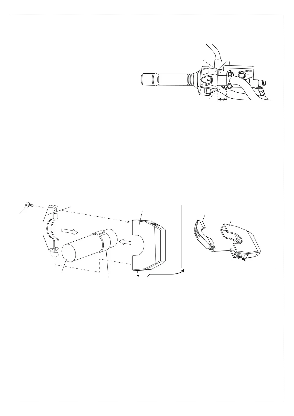
[Sample installation:
Between clutch master cylinder and handlebar switches]
※
Be aware of the vehicle wiring.
※
Make sure that there is no improper
contact with the lever or other parts.
Adjust the positions of
the clutch master cylinder,
handlebar switches, etc.
Provide a space of
15 mm or more.
[Assembling the USB power supply body] [Assembly precautions]
Φ22.2 mm handlebar(
※3
)
Opening
①
USB power supply body
②
Underbracket
④
Screw
Tab
⑤
Rubber band(
※3
)
※
3...Cut to adjust the length to the installation location.
On a Φ25.4 mm handlebar (or pipe), install without the rubber band
⑤
.
※
When installing beside the master cylinder or handlebar switches, be sure not to pinch the wires of switches and other electrical
components. Also, make sure that the lever, when fully squeezed, does not come into contact with the product.
Turn the handlebar to the left and right to check that the wires are not pulled.
①
USB power supply body
②
Underbracket
Opening
Tab
04. Use the screw
④
to temporarily assemble the USB power supply body
①
and underbracket
②
onto the rubber band
⑤
.
At this time, insert the tab on the underbracket
②
into the opening in the USB power supply body
①
.
※
Remove vehicle parts if necessary for performing the work.
※
Be sure not to pinch any wires.
05. Slowly tighten the screw
④
until the USB power supply body
①
can no longer turn.
※
Be sure not to overtighten the screw
④
. Since the product is made of resin,
tightening the screw more than necessary may cause the resin to crack or may damage the screw threads.
【
Connecting power supply wires
】
When using the brake switch branching wire harness
⑦
to supply + power
06. This can be used if the connector of the wire connected to the brake switch is L-shaped as shown in the diagram.
※
This cannot be used if the connection is made with a coupler. In that case, skip to step 17.
07. Connect the cable to the negative battery terminal. Of the two wires connected to the brake switch,
use a tester to identify the wire that carries 12 V when the ignition switch is turned on. After confirming,
turn off the ignition switch and disconnect the cable from the negative battery terminal.
※
If incorrect connections are made, abnormal operation, such as power being supplied only when the brake is applied, will occur.
08. Refer to the diagram below and connect the brake switch branching wire harness
⑦
to the wire identified in step 07.
【
Checking the installation location
】
01. The thickness of the USB power supply body
is 14 mm. Provide a mounting space of
approximately 15 mm on a straight part of
the handlebar.
02. During installation, refer to the diagram below
and make sure that no parts will come into contact
with the USB power supply body within
the provided space.
※
If there are parts that may come into contact with
the product, make adjustments to the vehicle
or install at a different location.
 Loading...